(click any image below for enlargment -close new window to return)
Prewar replica Speedster Build
page under construction June-Aug '25 - refresh browser for latest update
Being an old school Land Rover owner, enthusiast & modifier, my attention was caught by the Bentley-ish Land Rover 'Special" that Bill Hayfield built a few decades ago and I thought to myself I might like to build something similar one day.

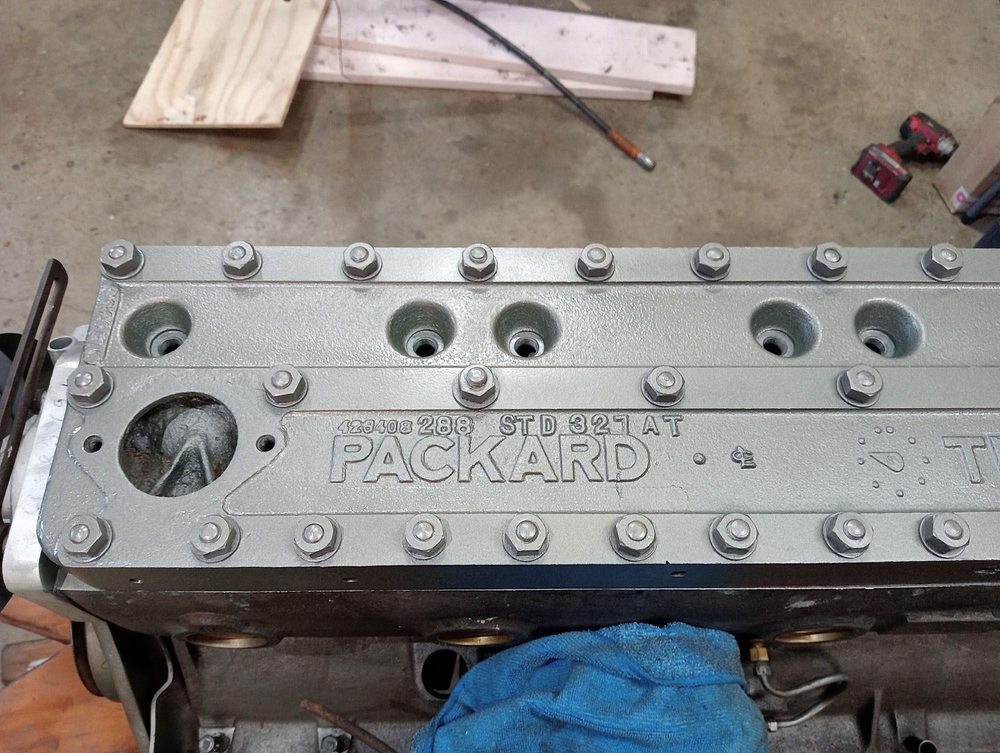
Packard Engines
Fast forward 30 something years and I saw some 'condition unknown' Packard Straight Eight engines advertised locally on Facebook marketplace for a price too good to ignore, now being a Land Rover & old Chrysler enthusiast the last thing I ever thought I'd go shopping for was anything Packard , but when it comes to anything "straight eight" beggars can't be choosers. -.
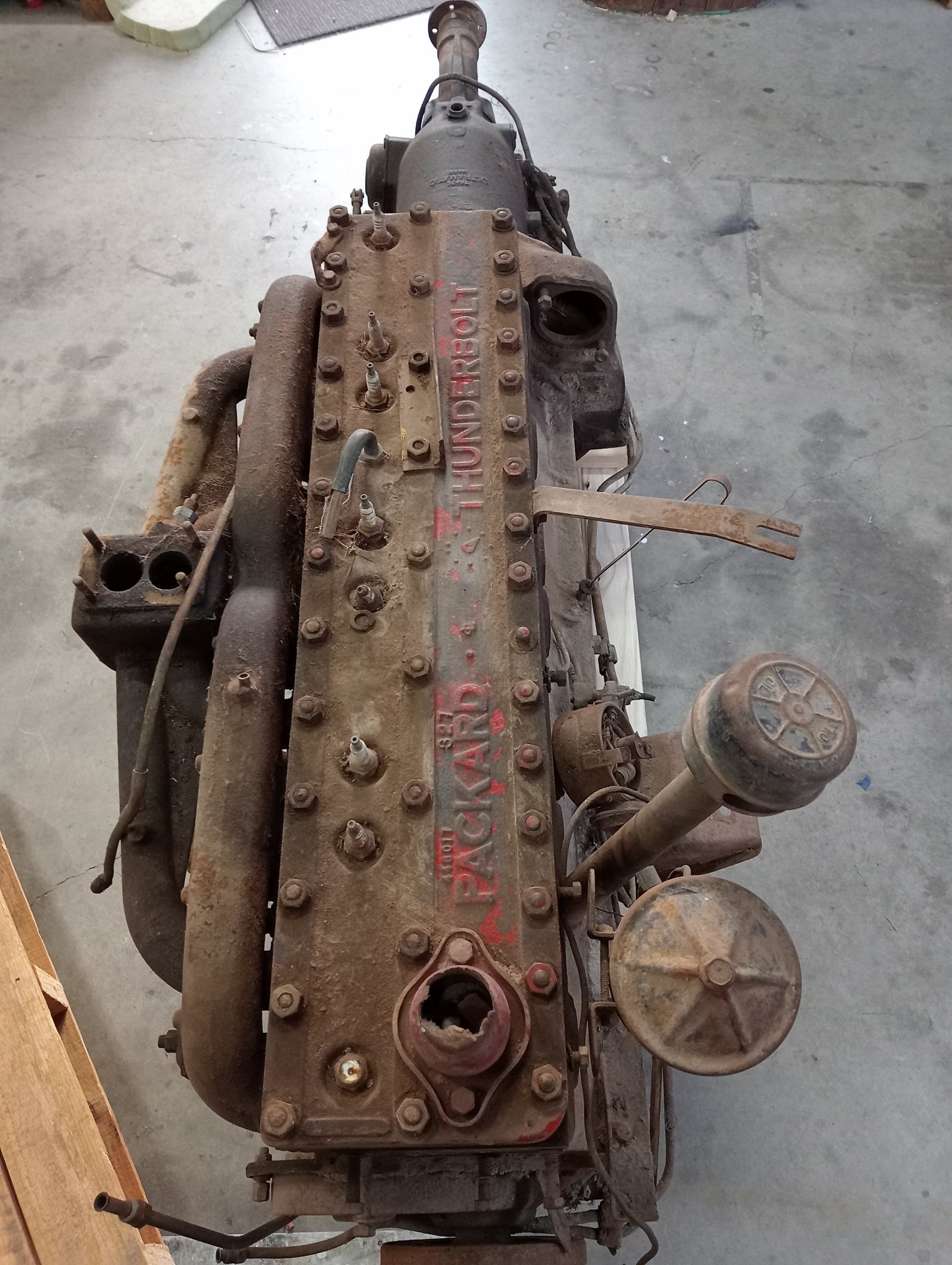
I decided strip the engines to see if there was enough parts to build one engine without an expensive rebuild. All engines had standard bores & cranks, The third engine had a reasonably good crank and bearings and the fourth engine had reasonably good bores. I chose the best eight STD pistons & ordered a new set of rings, timing chain and head gasket from USA. There was no Starter motor or water pump in my stash so I used what I had on hand and adapted a Holden Red water pump & modified a Toyota Hilux starter to fit ( Toyota 9 tooth starter pinion gear was copied from Vintage Chrysler and as is a match with Packard too) .
While working on the engine the build direction was evolving. Reading through various regulations including ASRF (Street Rod) and VSB NCOP (Vehicle standards bulletin) using a Land Rover chassis would be a straight forward path but needs VASS engineer consultation and expense, not really any viable option in Northern Victoria. So I decided to build to VSI-33 which pertains to pre-1949 Cars , the rules are more relaxed and allows the construction of a Replica on a period chassis using period parts without the need for engineer consultations and expense. (no modern engines or disc brakes) .
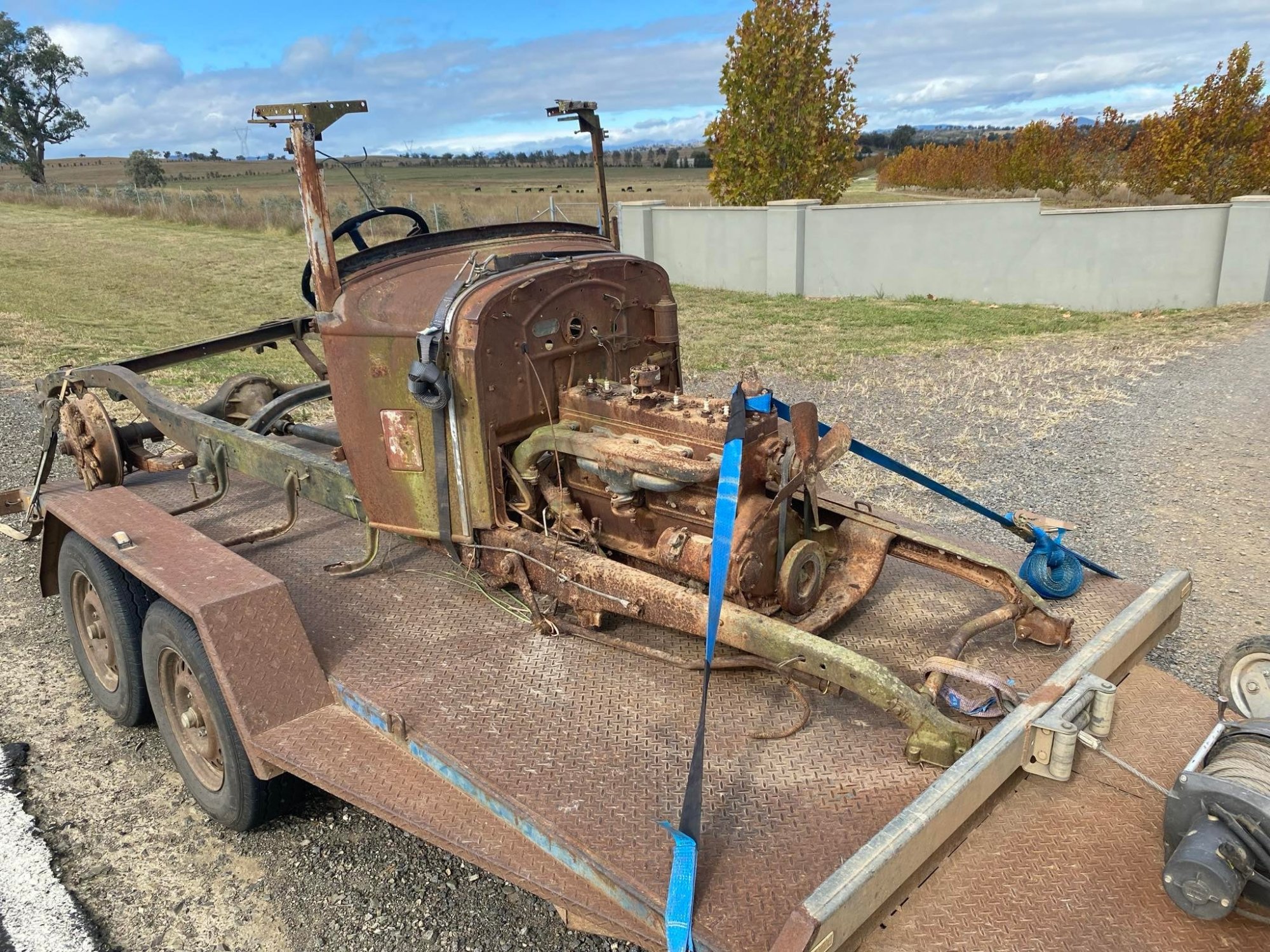
I now was keeping one eye open for a PreWar chassis to use and knew of a few in the area, I went to check out a late 1930's Fargo and 1929 Chrysler 75 on farms each of which provided some parts but the chassis I ended up with was another '29 Chrysler 75 series from Matt Lack in Dubbo & kindly dropped off enroute to the Bendigo Swap meet. .
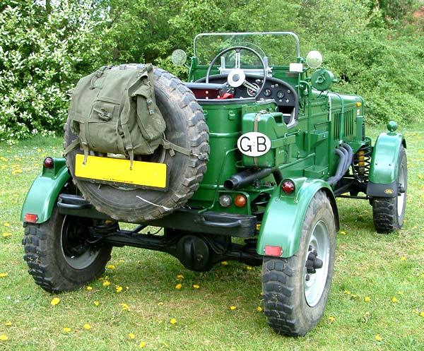
Railton Replica
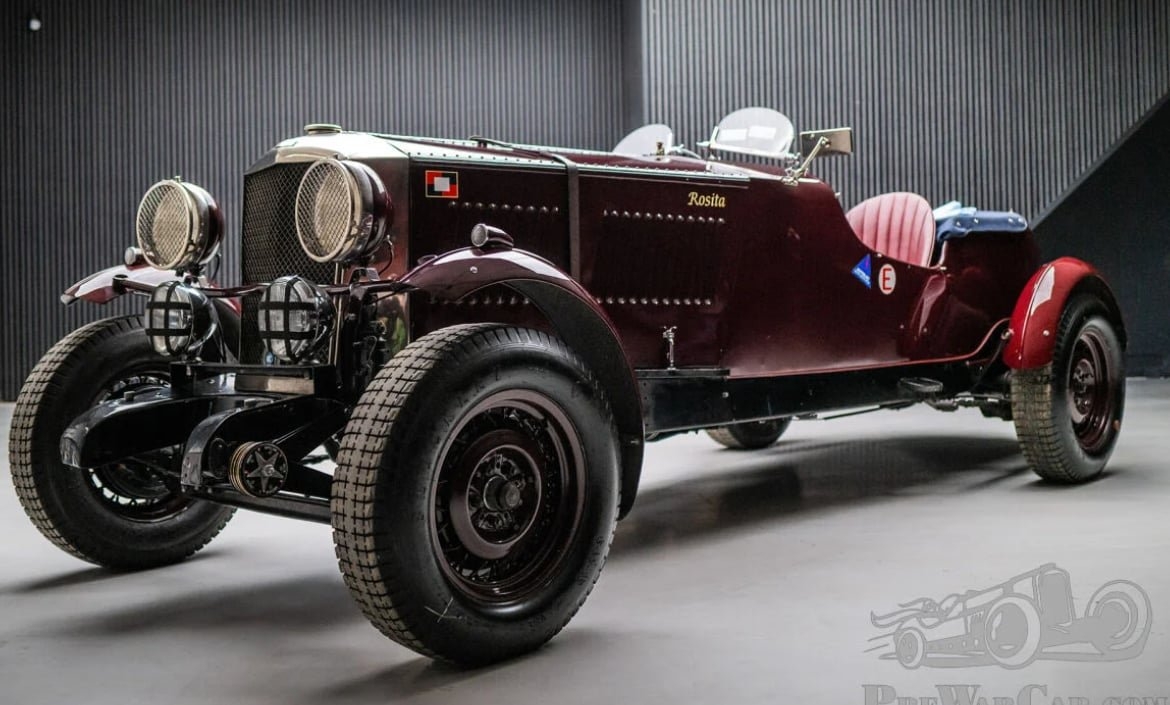
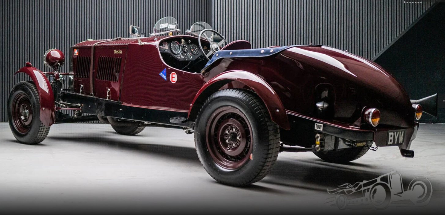
Now the goal is to end up with a car that is somewhat similar to the Railton pictured above. The Chrysler 75 chassis is 121" wheelbase only an inch shy of the Railton. VSI-33 allows for the build of Replicas but for Registration purposes the car will identify as a 1929 Chrysler, not that VicRoads would know one from the other
The Chrysler 75 has racing pedigree & was very competitive up against the Bentley of the day in 24 hour endurance races at Le Mans & Mille Miglia, so I'm happy to use the Chassis as the basis of the cars identity, and so it should be .
The Spring Cushions
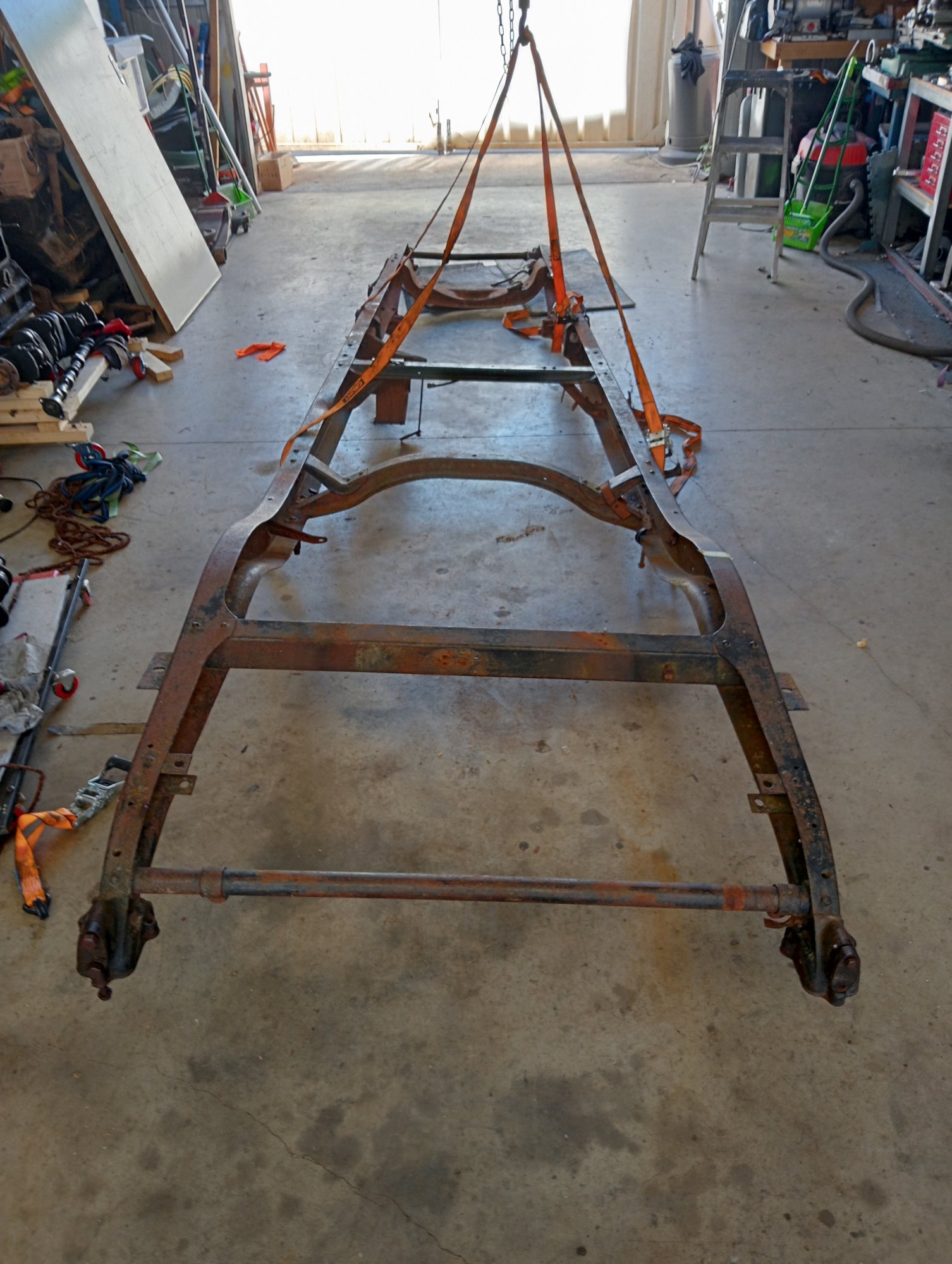
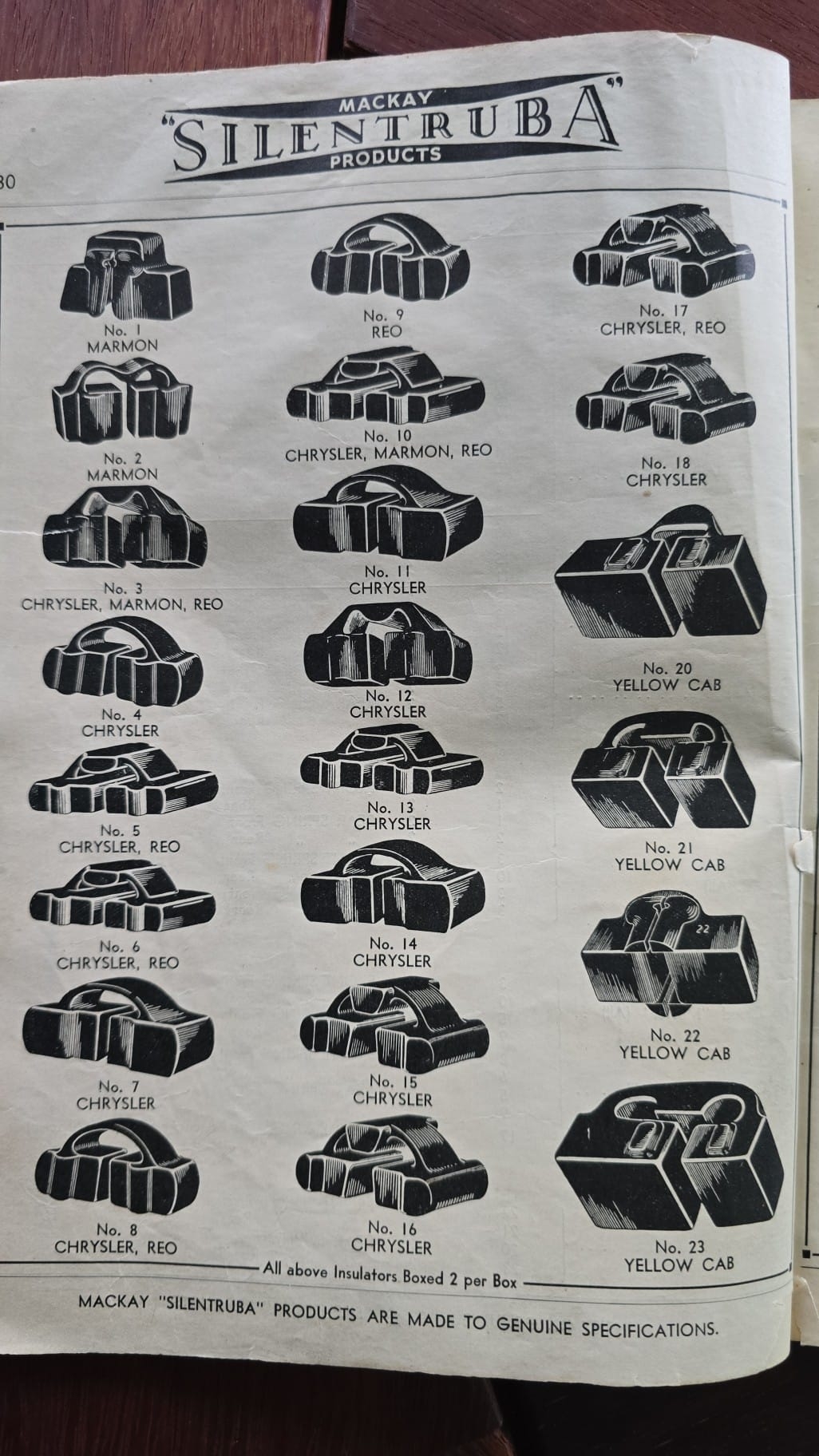
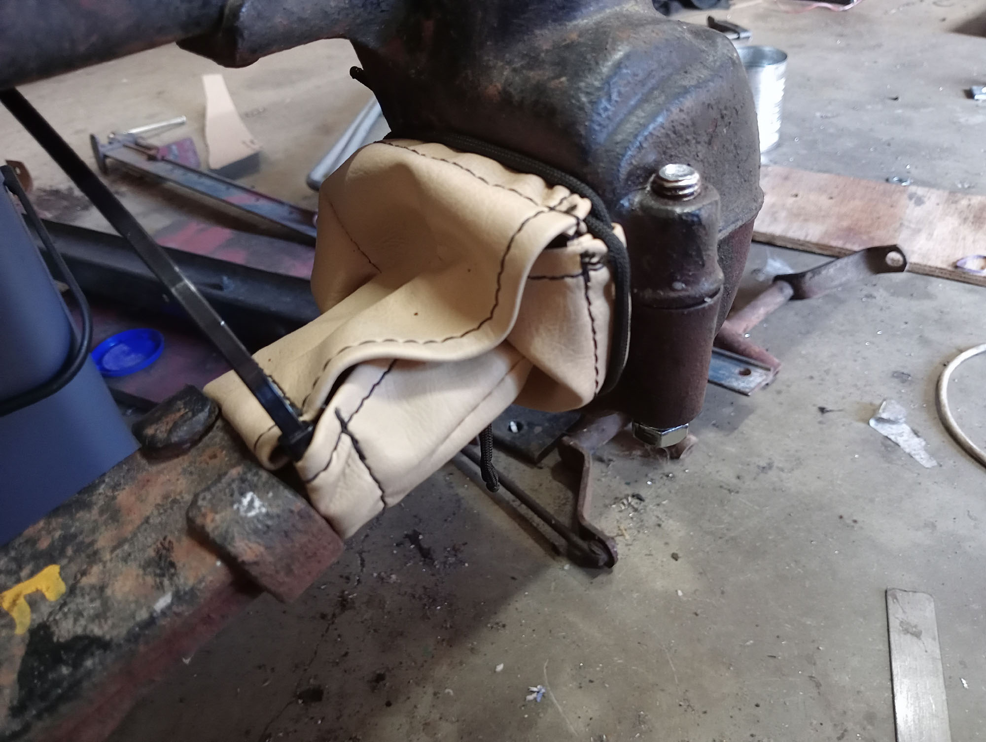
The most distinguishing and unusual feature of the 27 to 31 Chrysler chassis is that there are no traditional spring hangers. The Springs do not have spring eyes or shackles , instead the spring ends are contained in 'Spring Cups" with rubber cushions. This is problematic because the rubber spring cushions have not been available for decades. This is something I need to address before getting too far into the build, one option is to convert to traditional spring attachment methods, but I do not want to lose the identity of the chassis by altering this remarkable feature,
When I say the spring cushions are not available, well, Steele Rubber USA list them on their website for around US$1000, but the will not supply them nor will they answer email enquiries about them.... Great way to run a business, There is nothing on any of the Chrysler user groups or youtube on how to make them though I do believe someone in Australia has moulds.
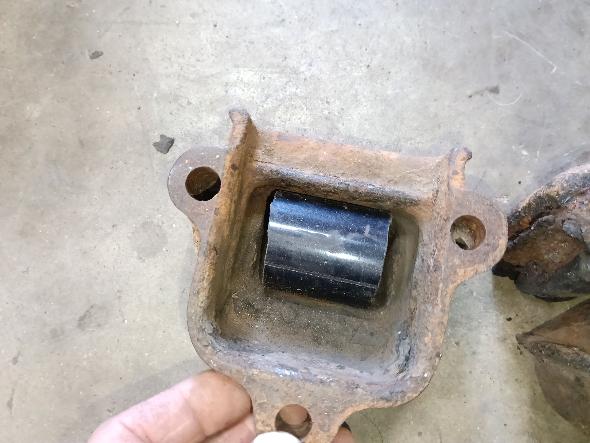
In all there are Eight spring cups on the Chrysler 75, Four one each side, Each spring cup is a different size for whatever reason and the rubber cushions are non interchangeable except for the same position on other side
Note: I'll go into a little more detail in this section of my build summary only because there is nothing out there in Internet land about these spring cushions & it may be useful for owners of this era Chrysler.
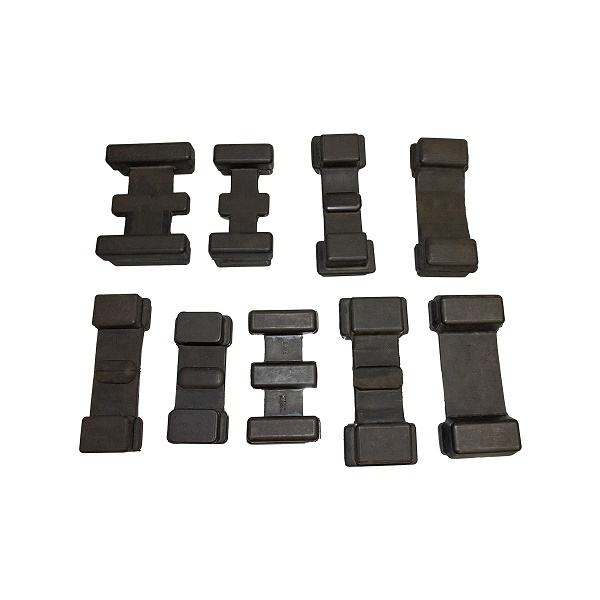
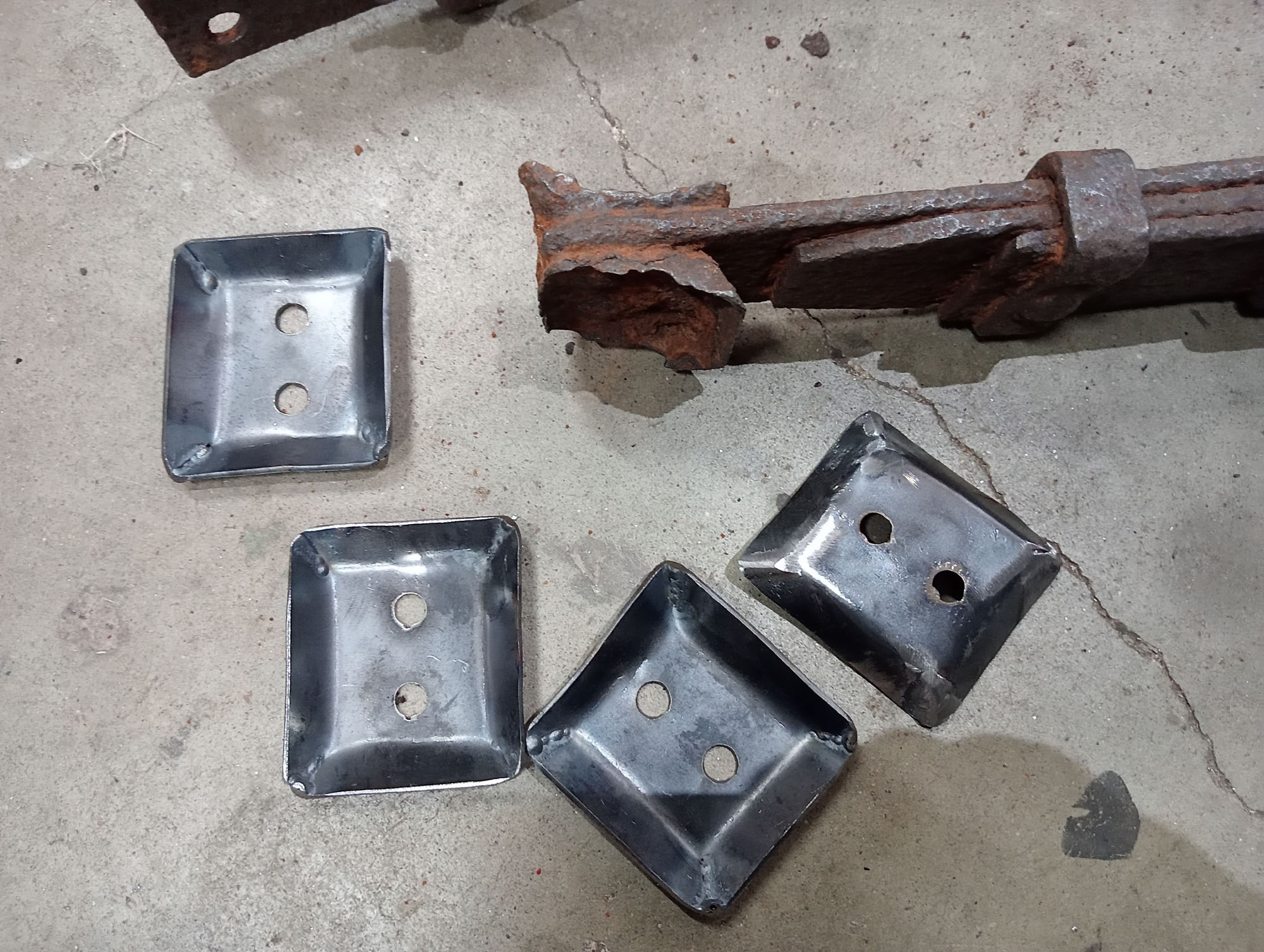
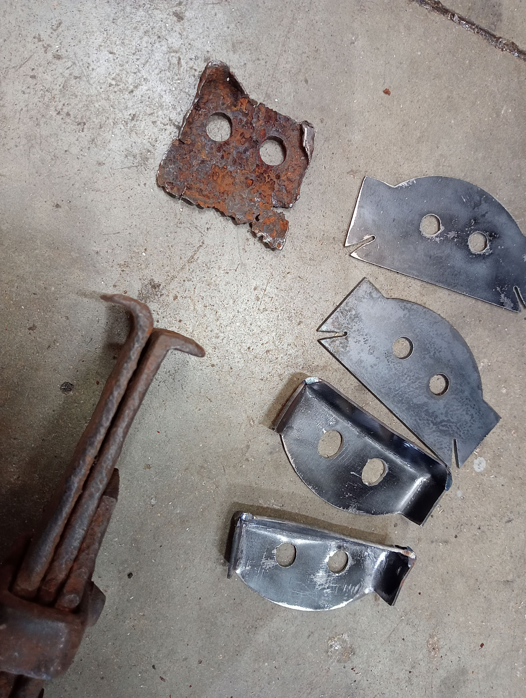
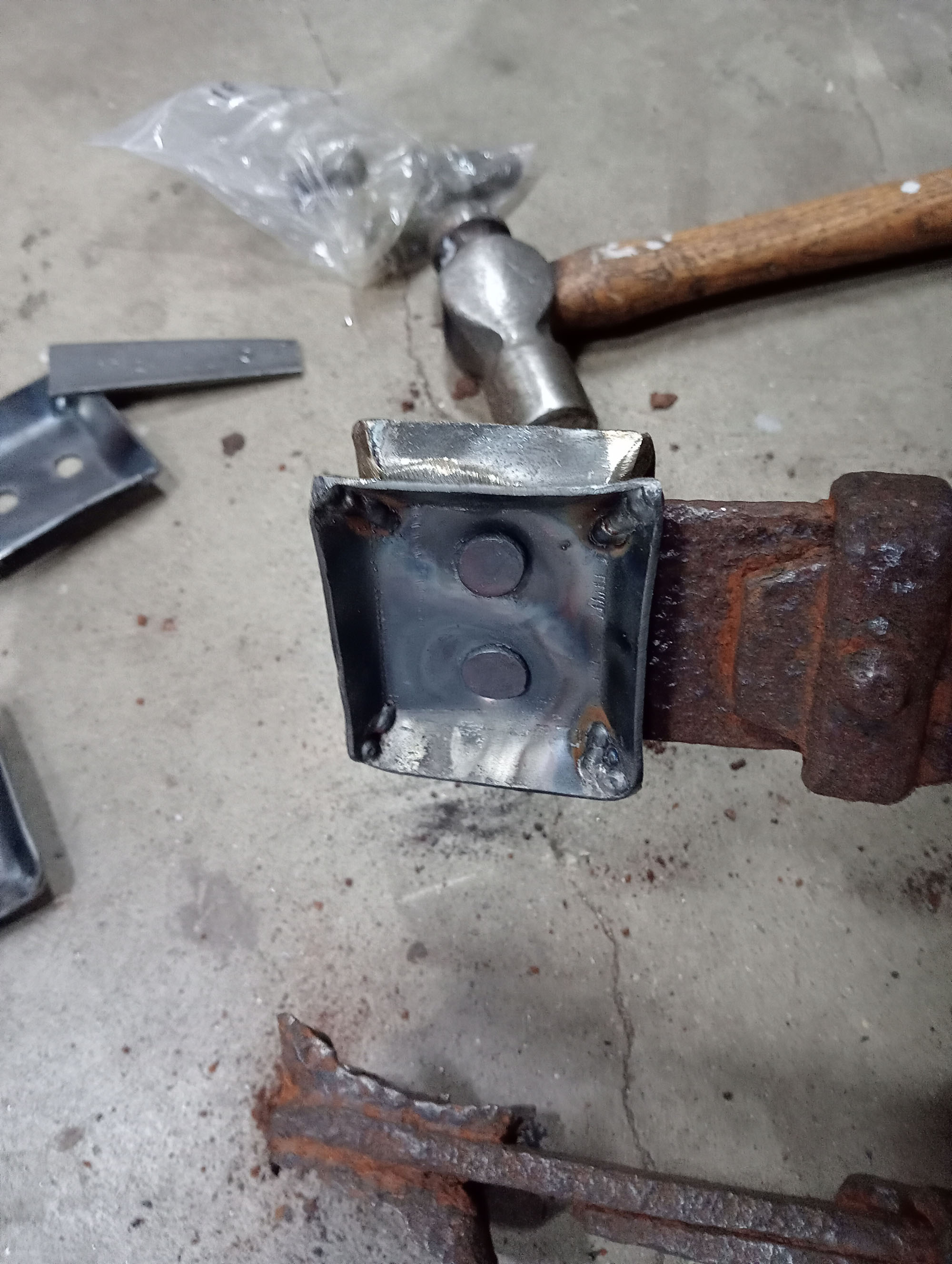
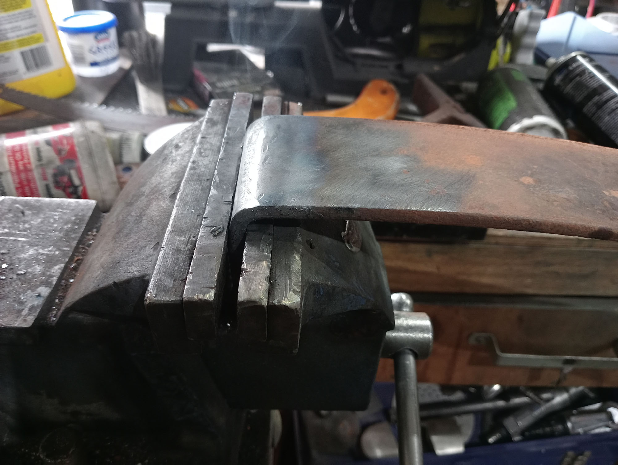
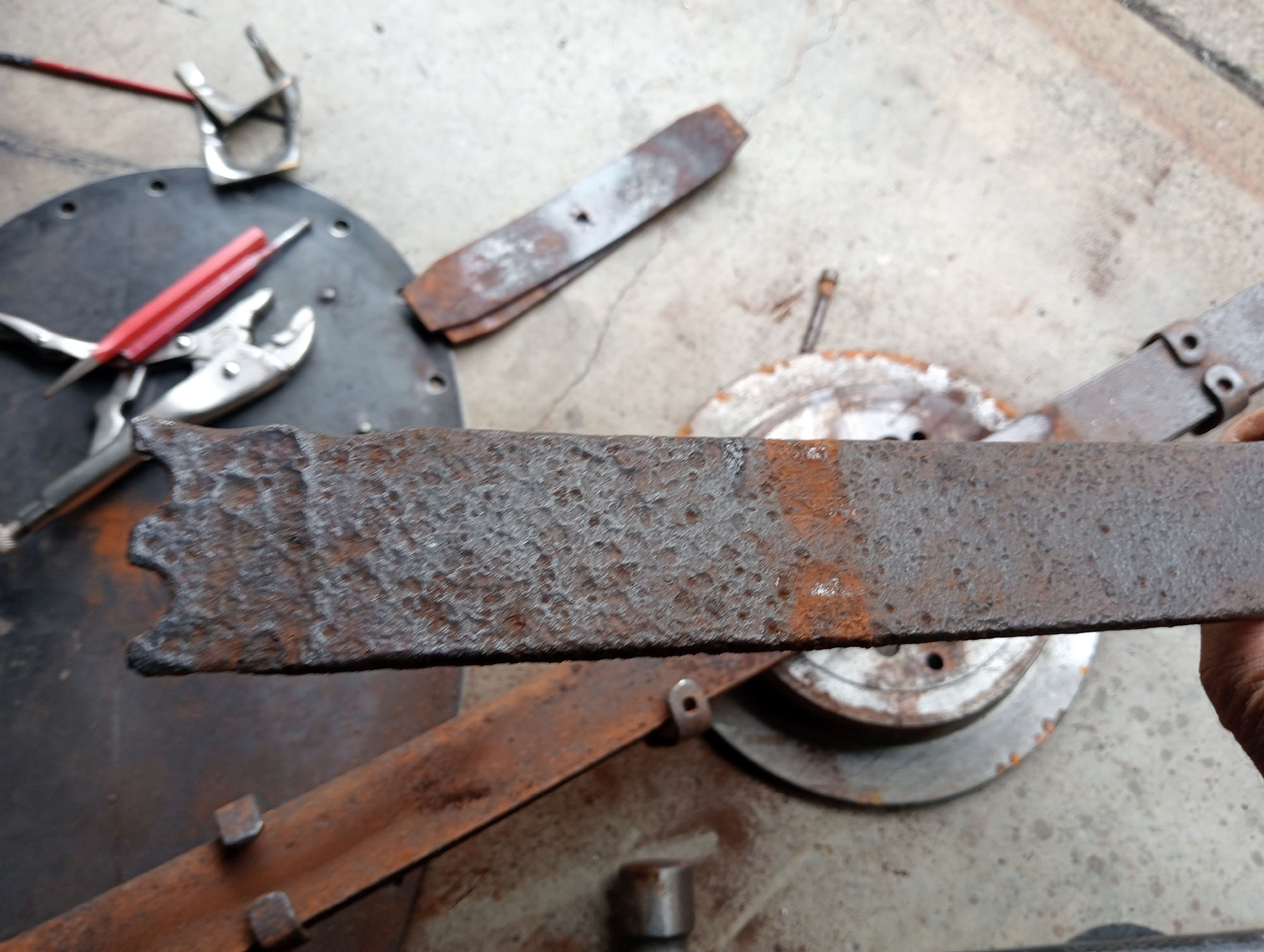
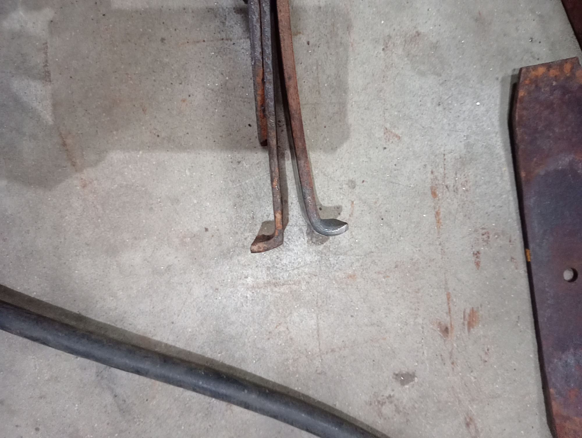
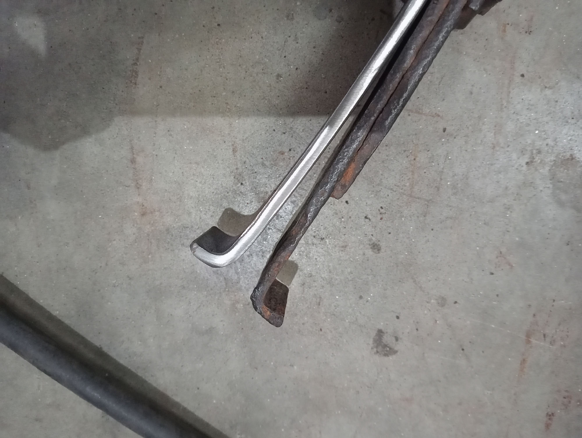
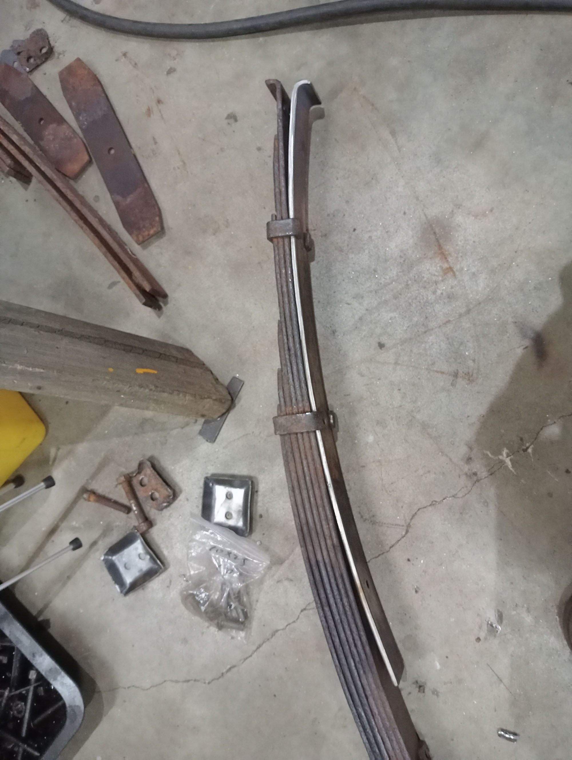
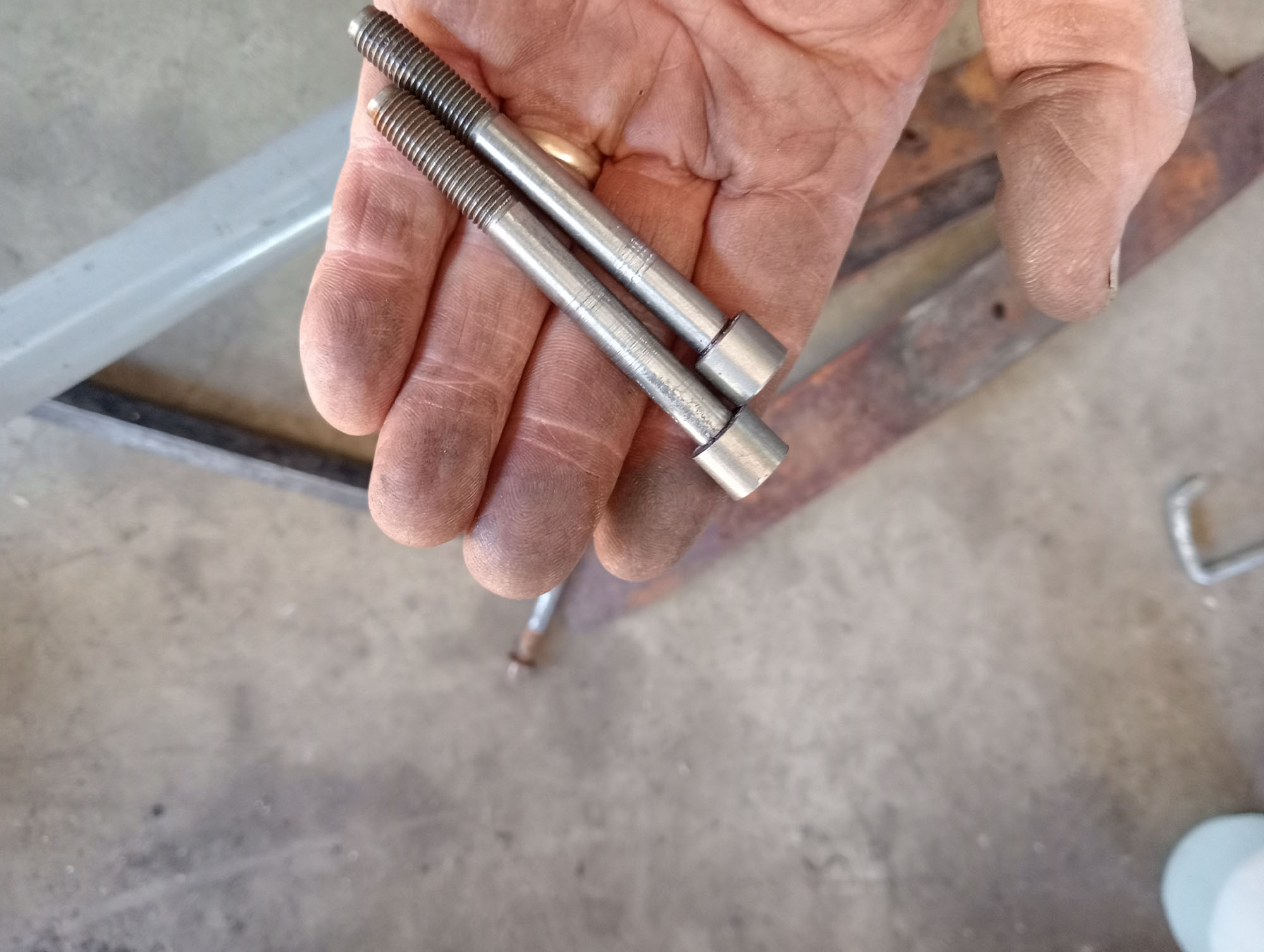
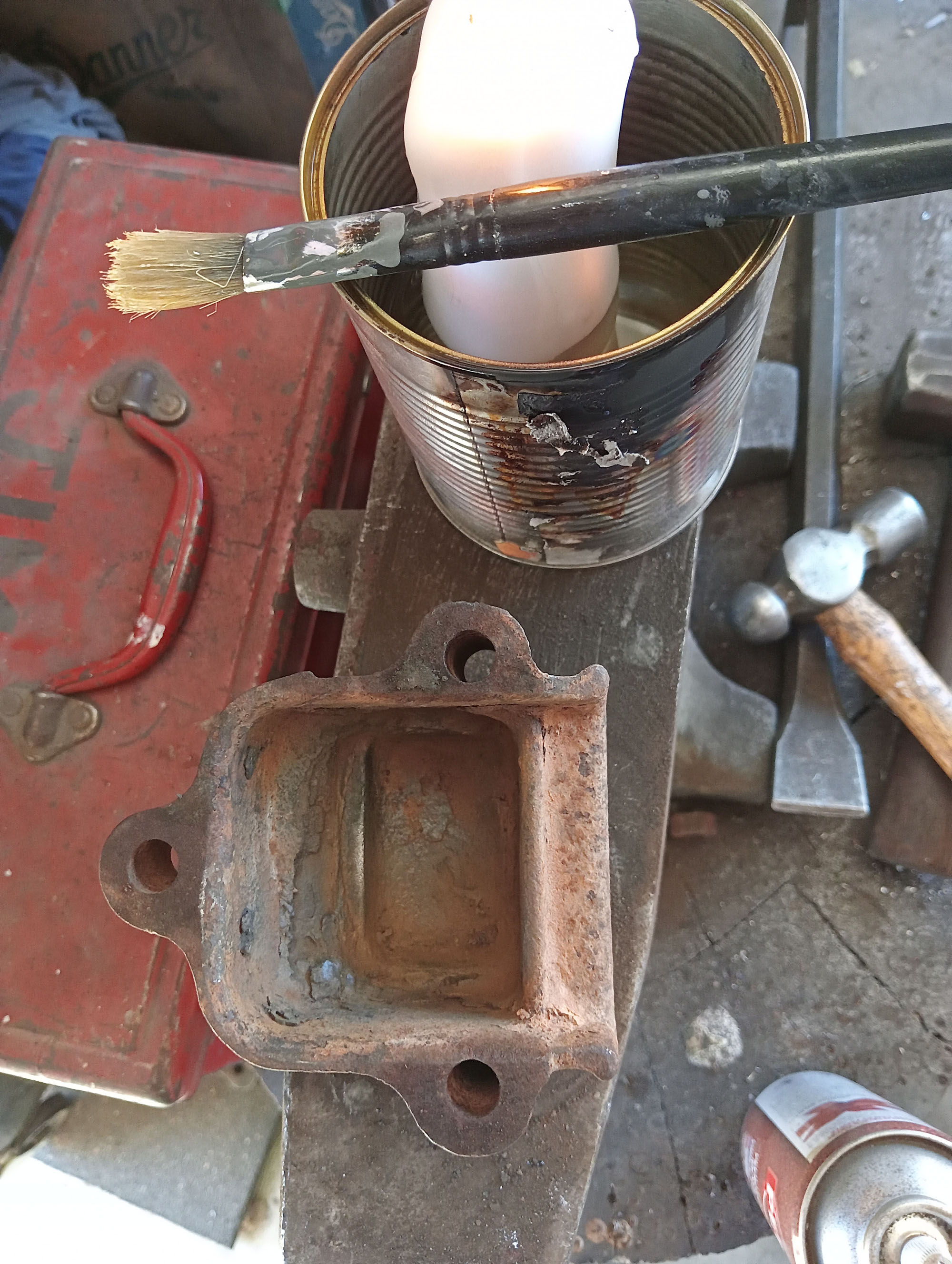
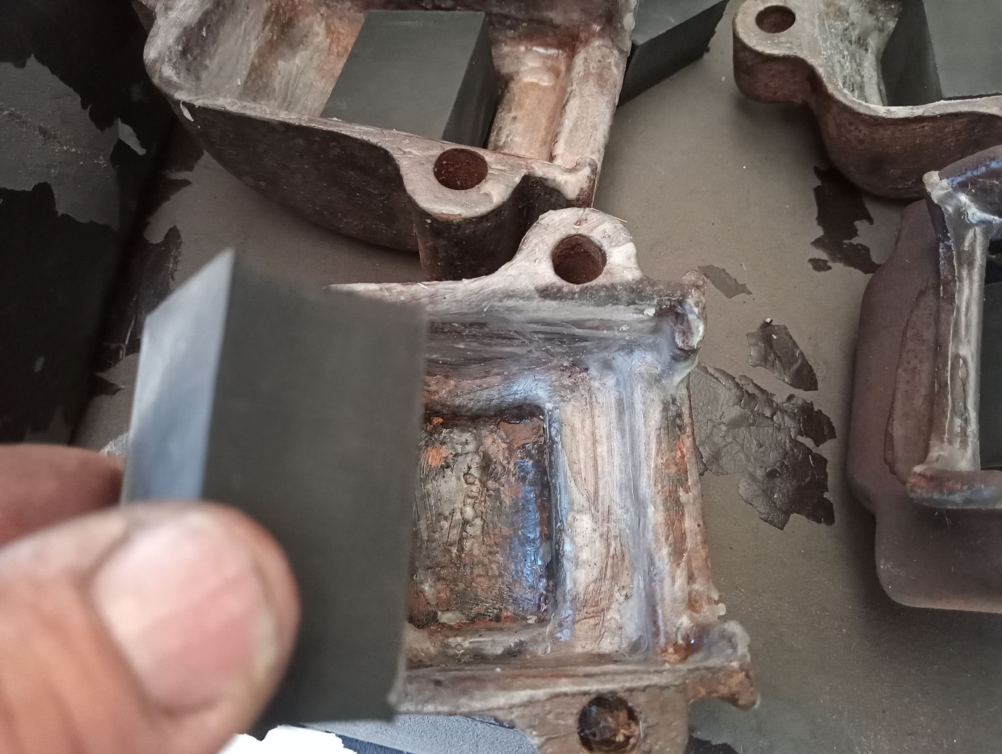
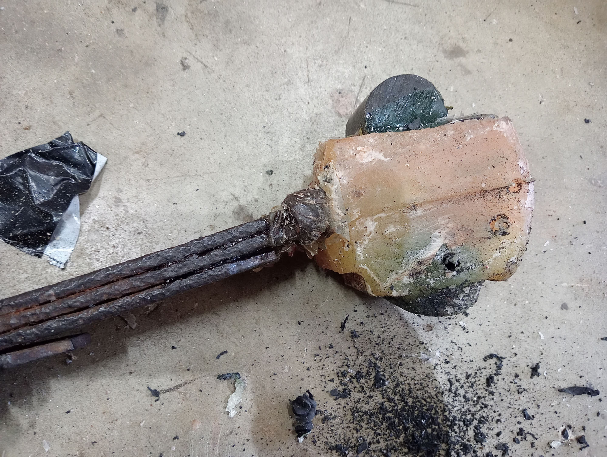
Fortunately Matt Lack provided me with a pair of rear springs with the bare chassis and I recovered a pair of front springs from a farm dump. The Ends of the springs have a sheet metal housing riveted to them, these were rusted beyond repair so I made new parts , and replaced one broken spring leaf by cutting down a Land Rover spring leaf. I also removed a few leaves from each pack & made new centre bolts. Per the following photos.
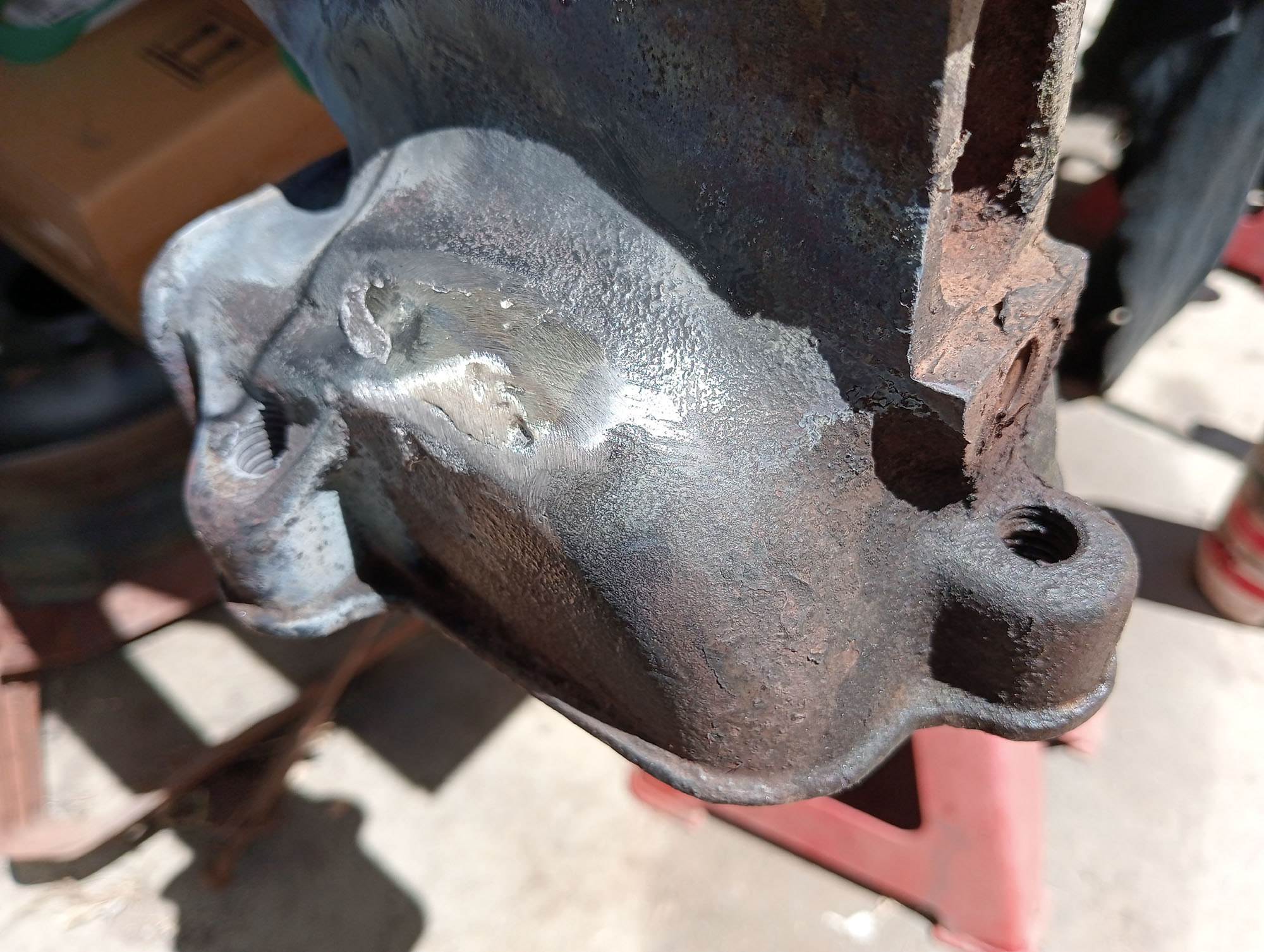
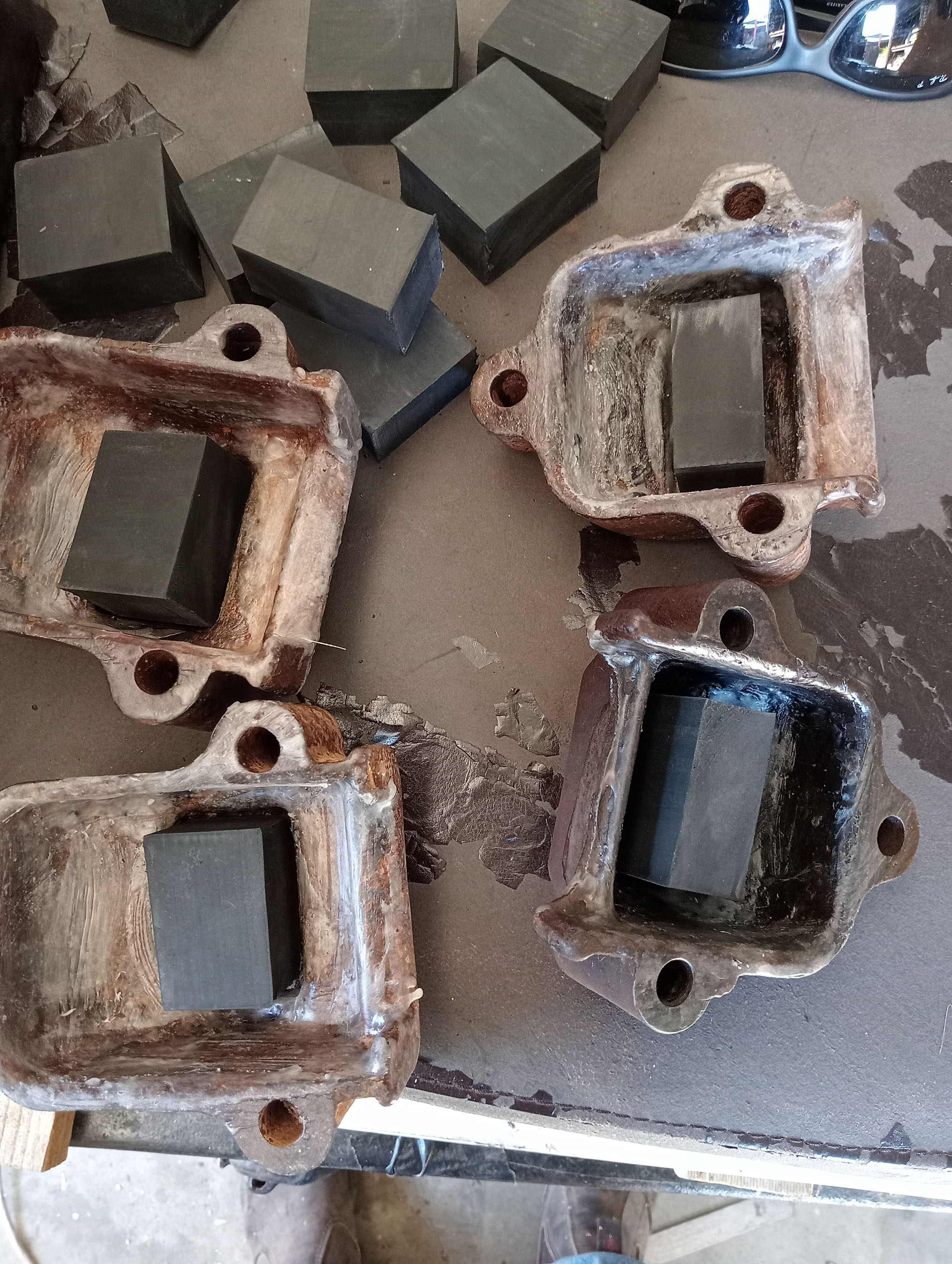
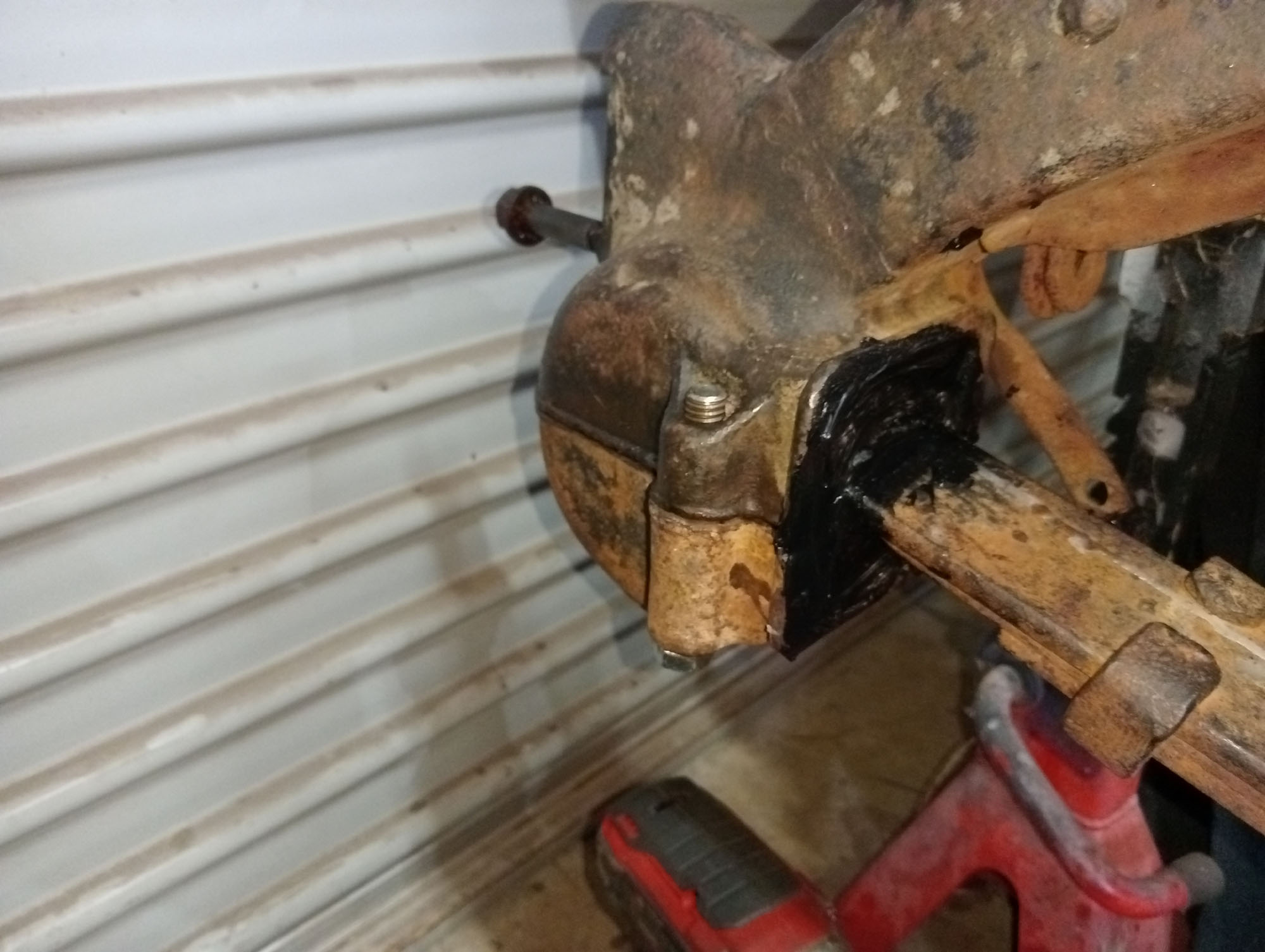
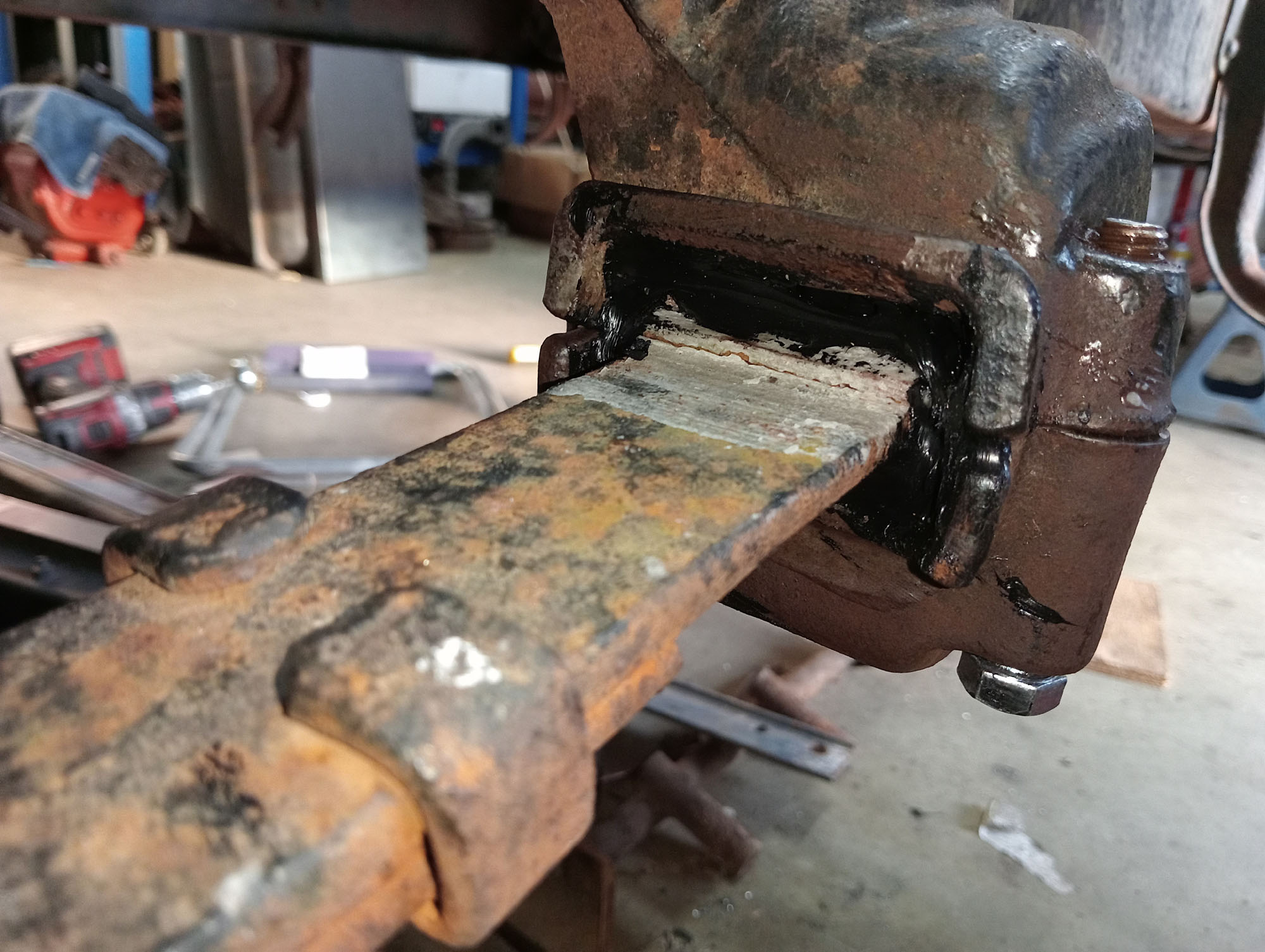
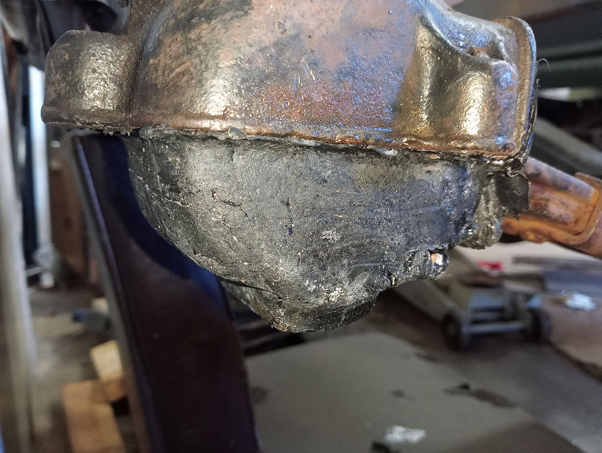
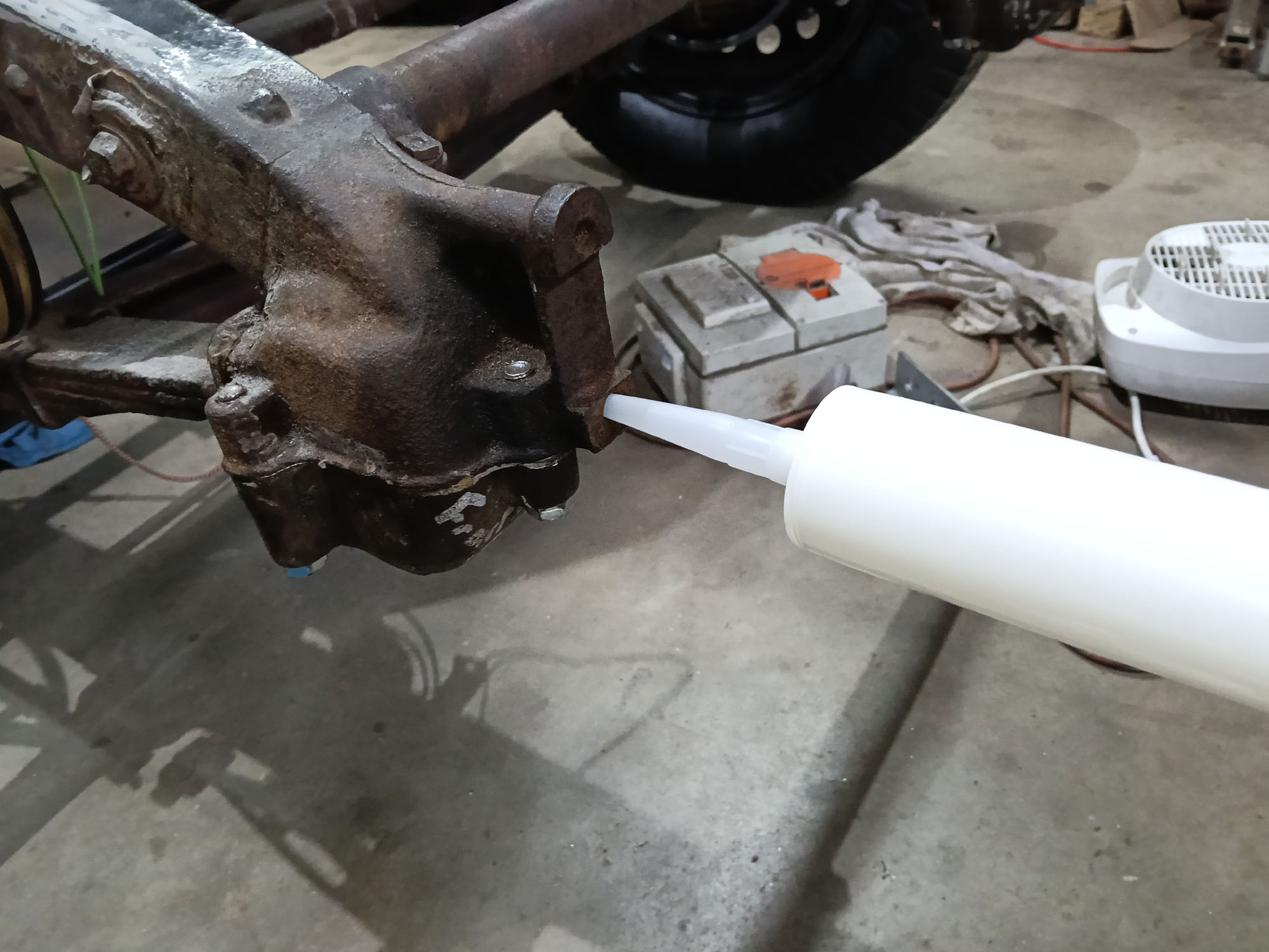
To make the Rubber cushions I put the chassis on jack stands , coated the inside surfaces of the spring cups and spring ends with melted candle wax (as a release agent) I cut some pieces of Shore65 EPDM rubber & placed in the hollow of the spring cups . I placed one spring into position & preloaded it with a jack and ratchet straps to simulate the weight of the car settled onto the spring then filled the spring cup with rubber compound. Its a very messy job.
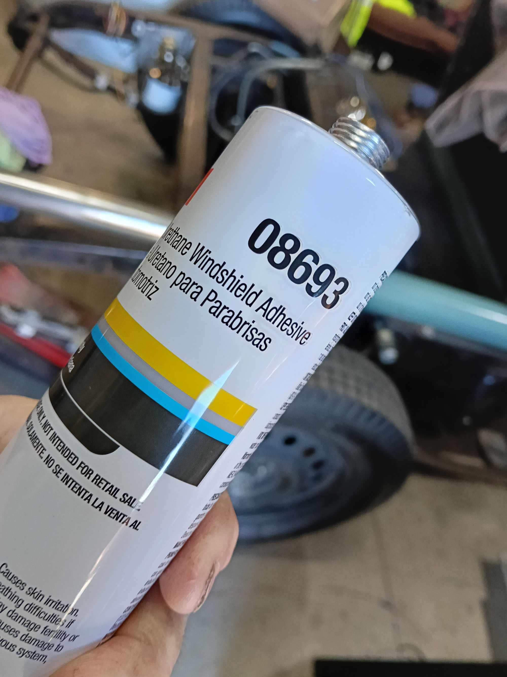
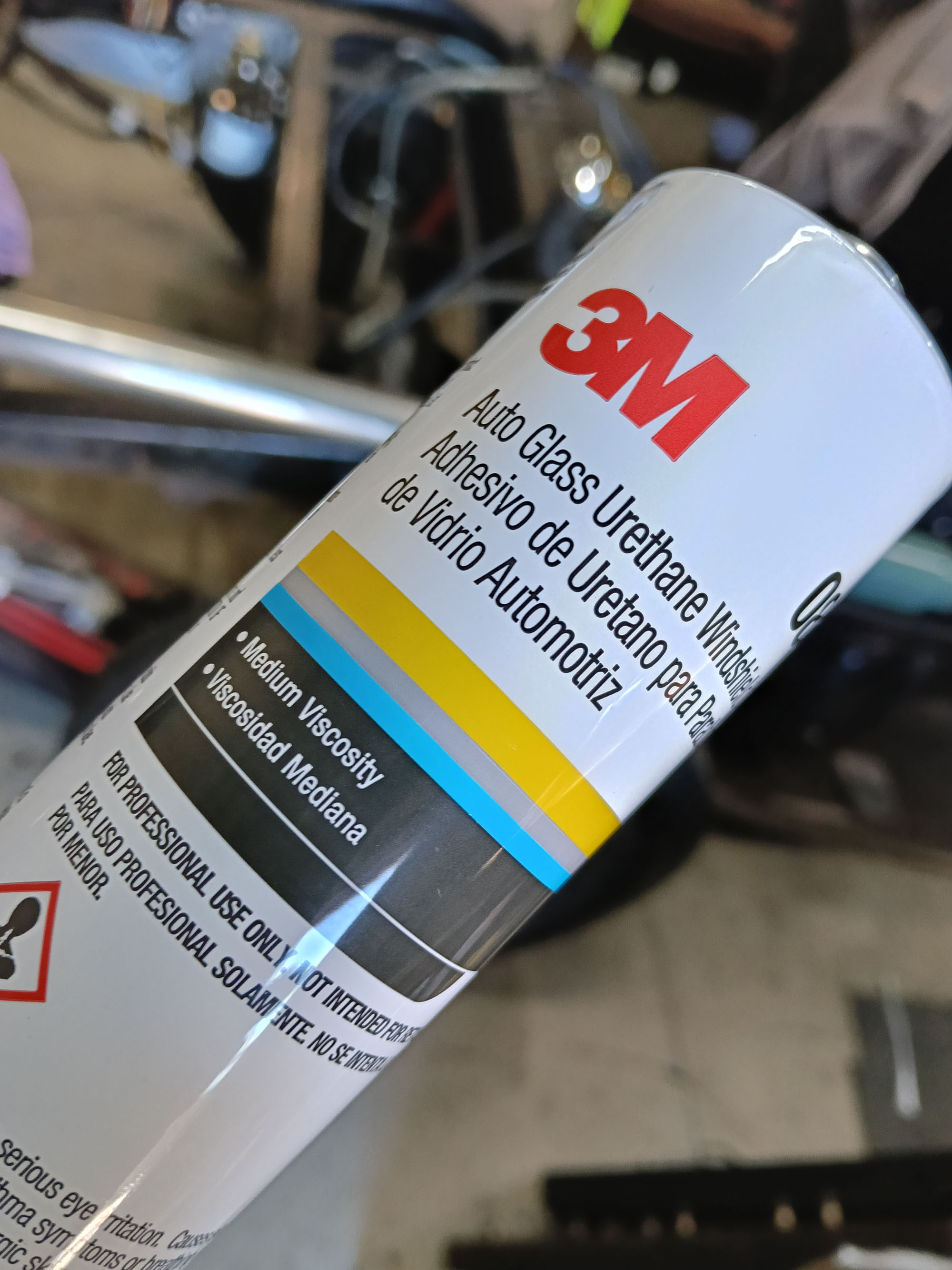
I tried 2 different rubber systems. The first was 3M 08693 aka 3M Windo weld (from Amazon) - this is a one part Shore65 Eurathane that cures on contact with atmospheric humidity. By design it is a flexible Auto glass adhesive, but in the youtube repair hack world people make engine mounts & suspension rubbers from it. I though it worth a try. In practice its a very slow cure - it takes about a month. I simply squirted it in & around the spring cup cavity then taped the visible holes to stop it leaking out
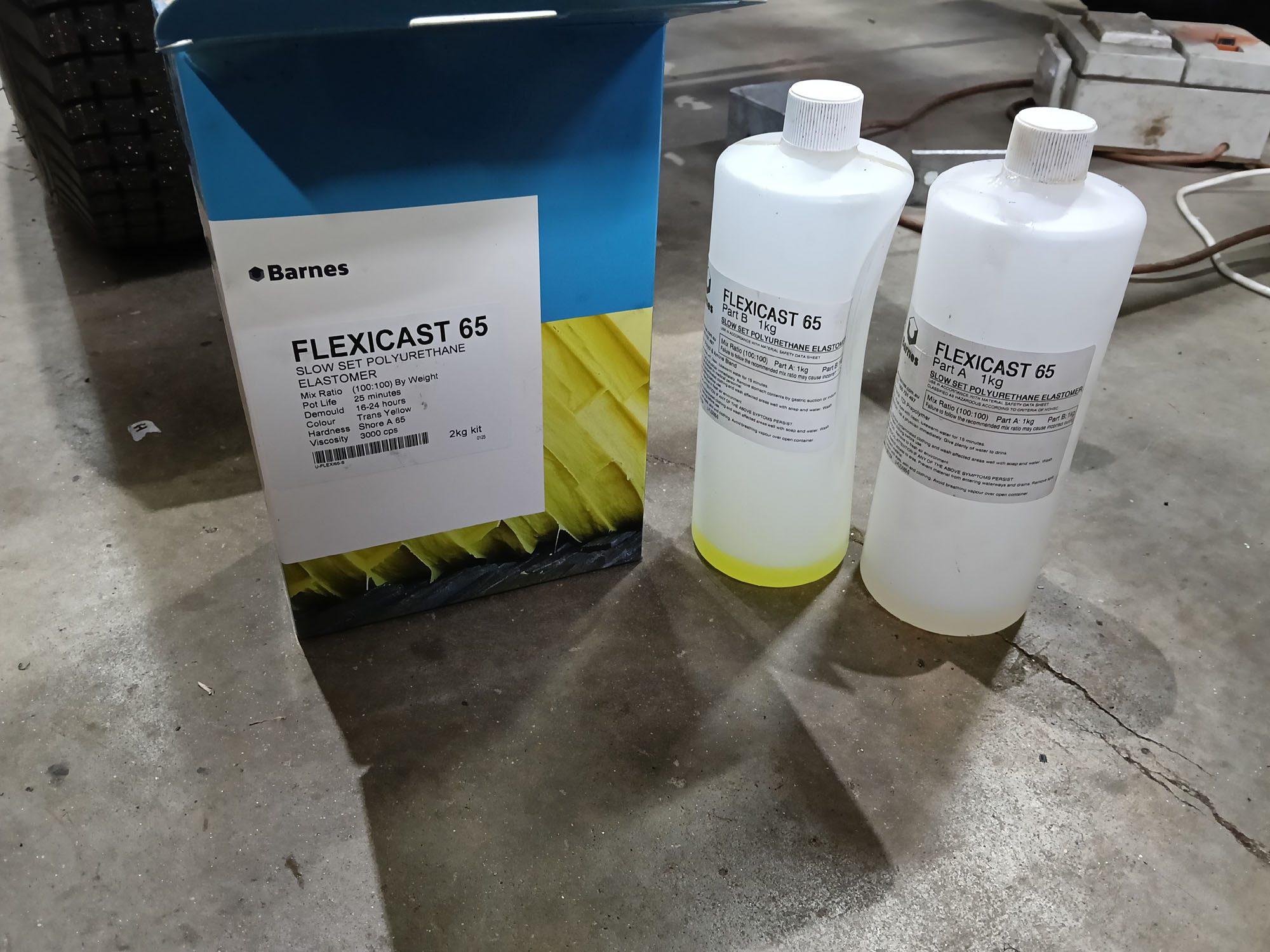
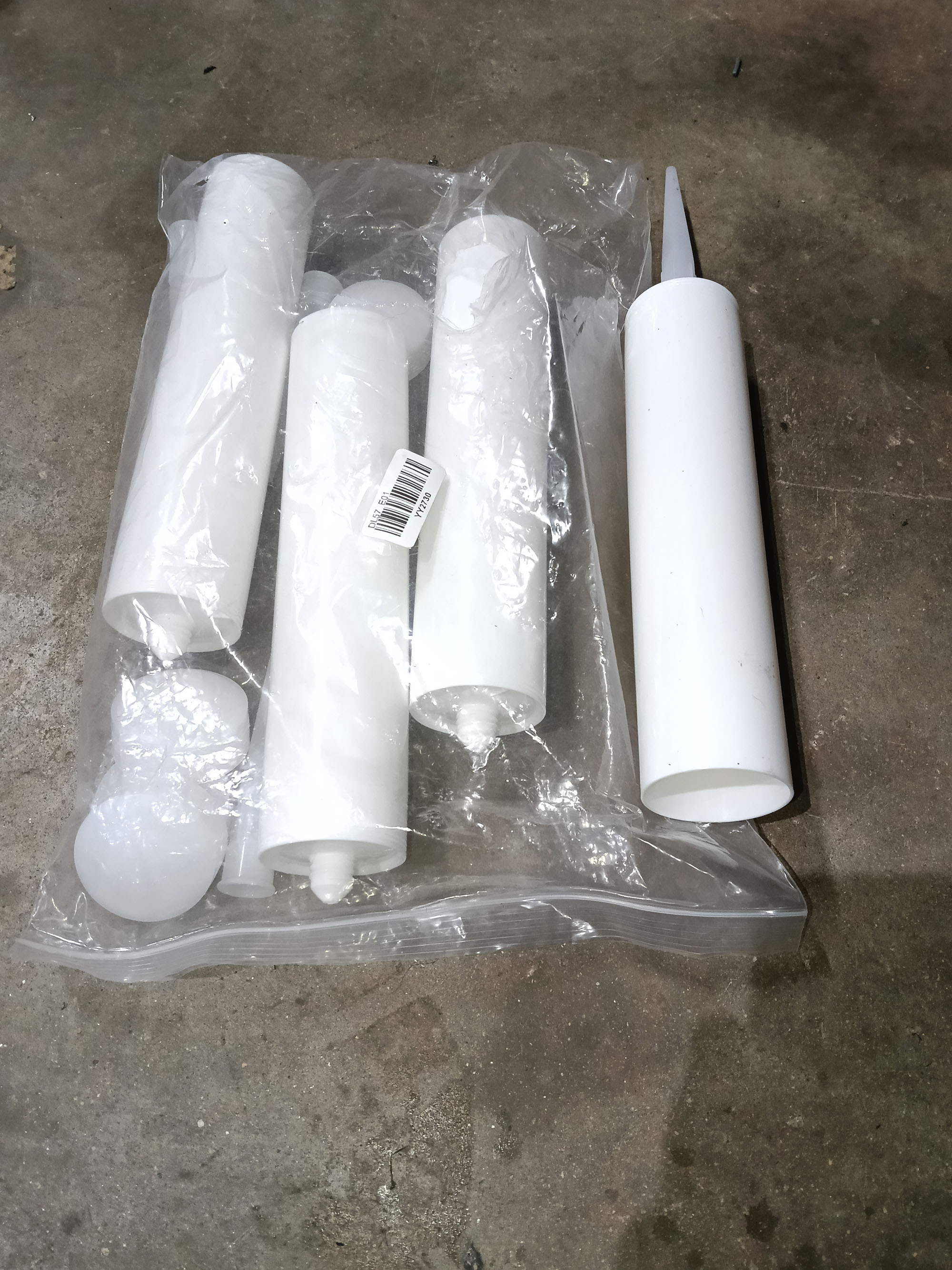
The other system I tried was a 2 part Polyurethane called Flexicast 65 from Barnes , again this is not a recommended use of the product. I mixed the Part A and B in a paper cup & decanted into a caulking gun. Work time is 20 minutes, One 300ml caulk tube holds enough product to do about 2/3 of a spring cup. This time I taped all around the spring cup & around the spring with duct tape & filled the spring cushion void through the lower bumper bar mount holes . This is very sticky & very runny stuff, & you constantly need to keep re-taping over the duct tape to stop it leaking out. It cures overnight.
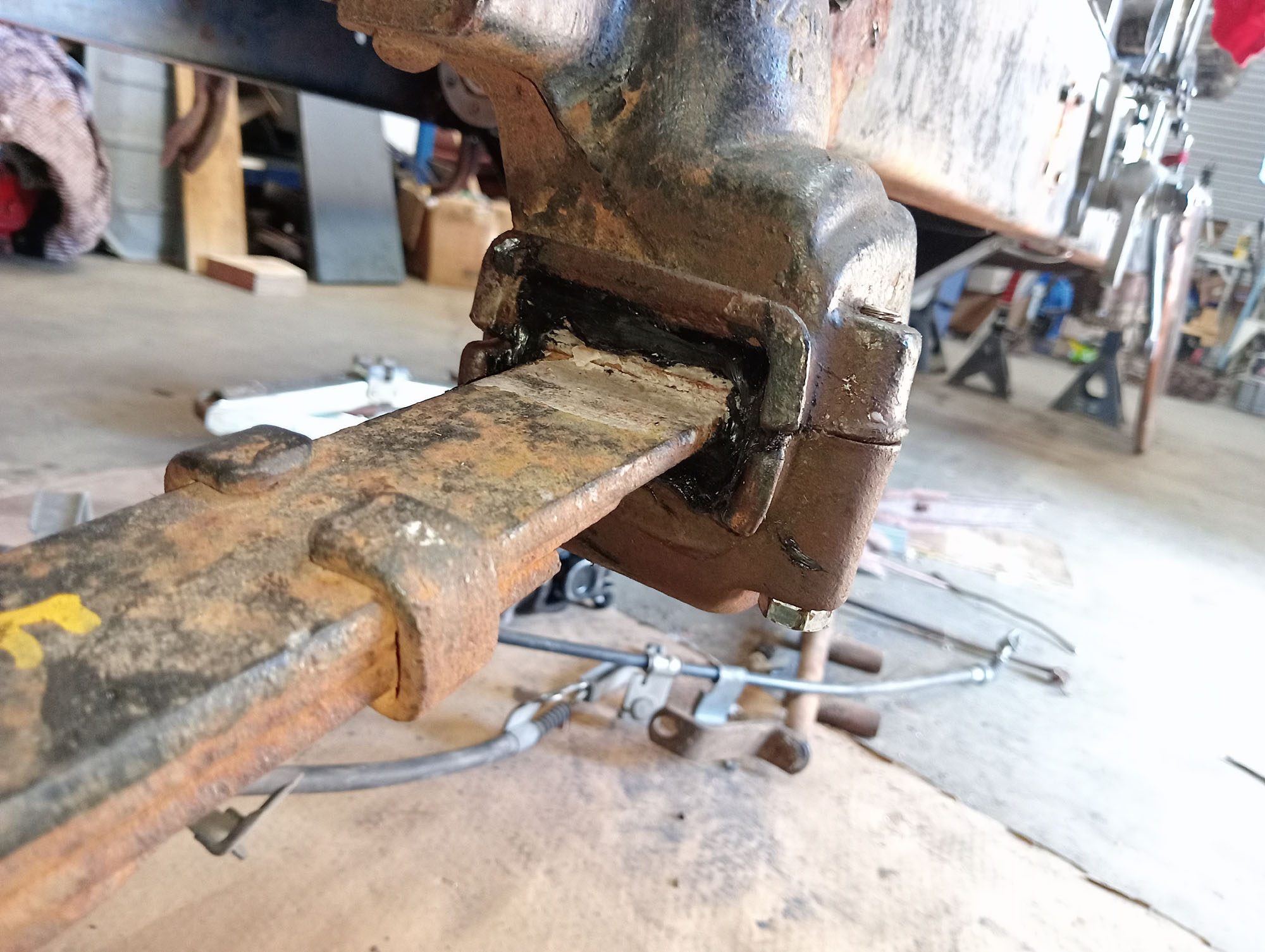
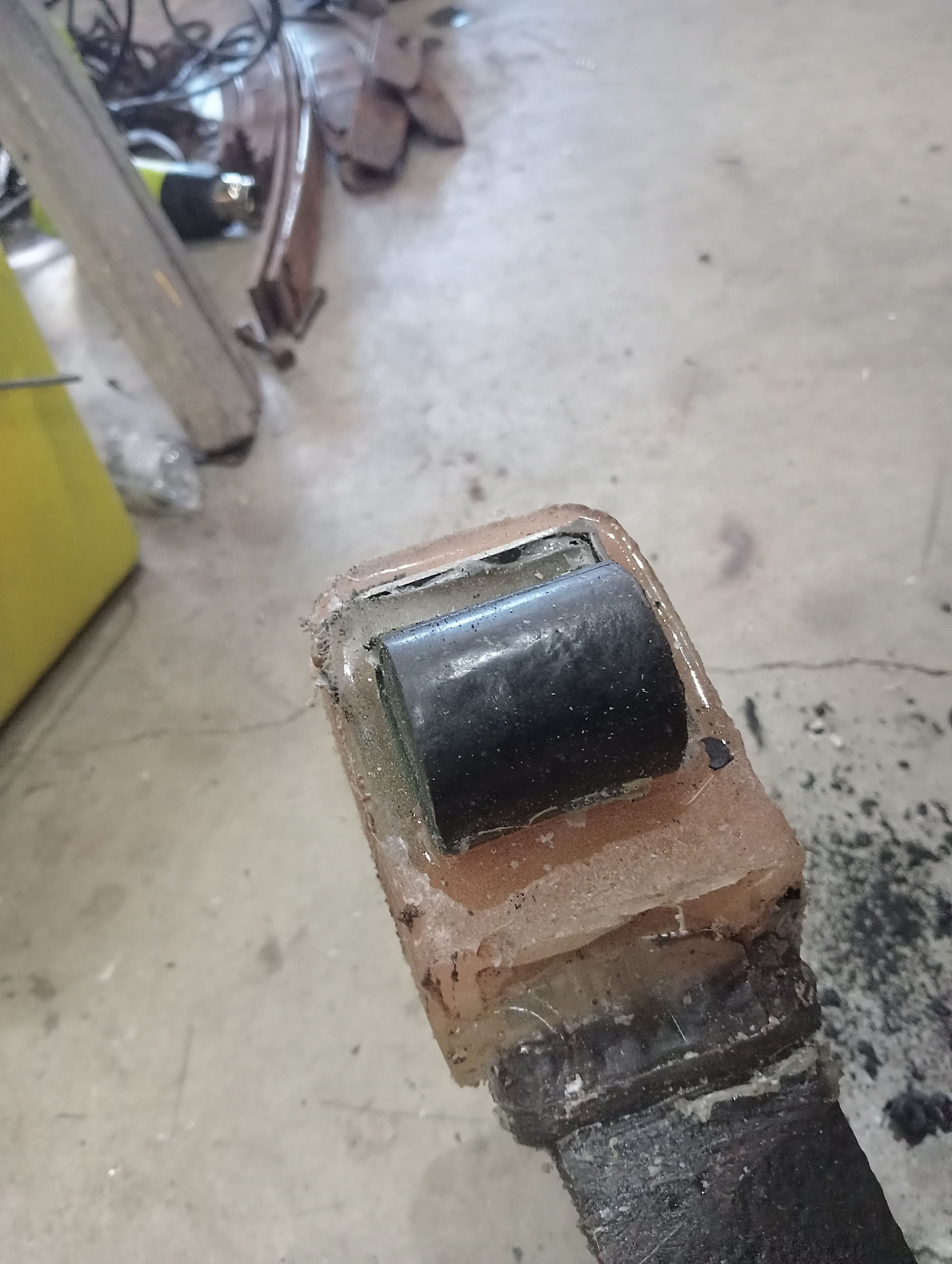
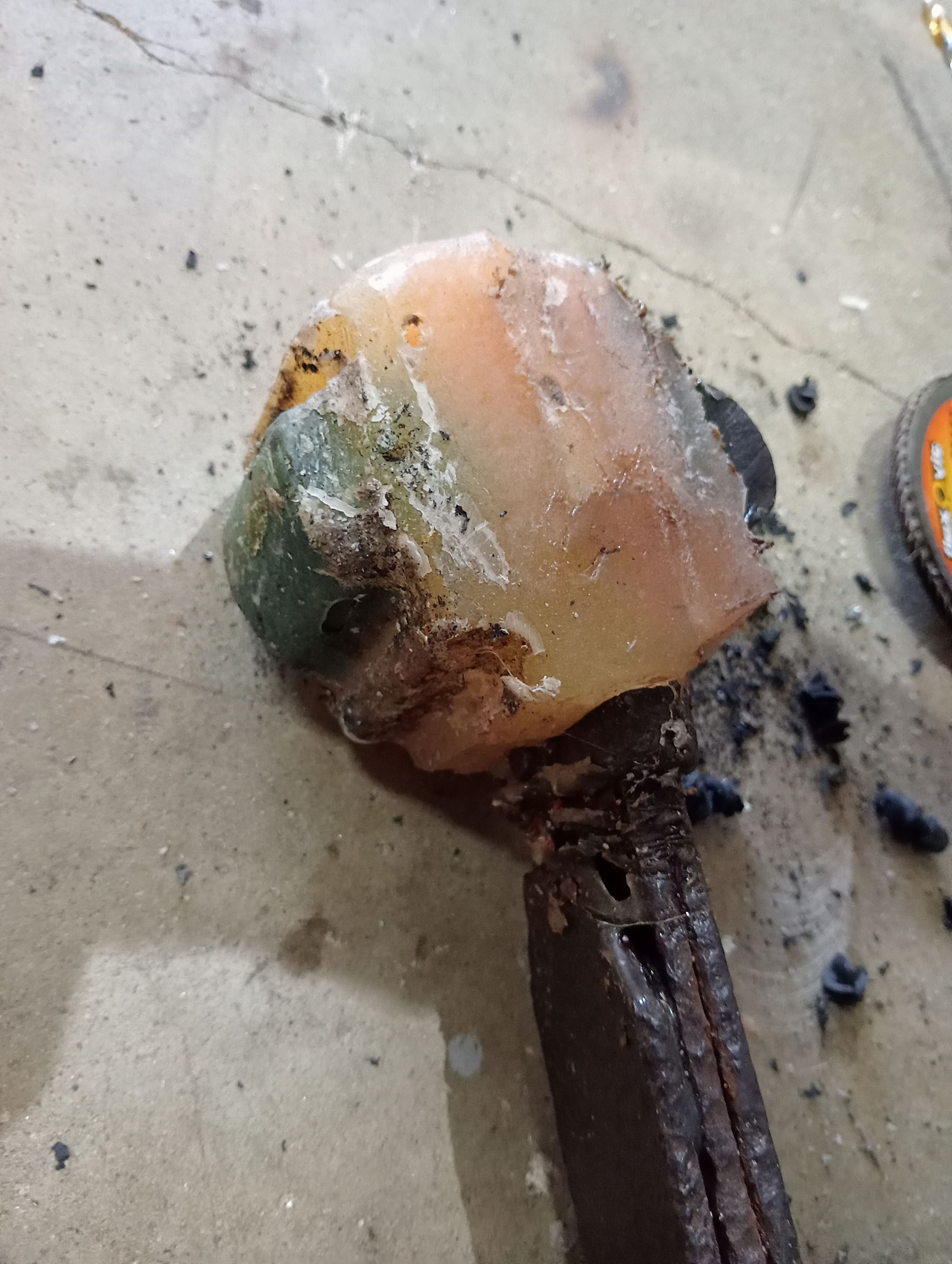
I don't know which method works best , if at all, The spring cushions seem very solid & the suspension does not have much bounce to it. I will need to drill holes in the cushions so that they have some give , but will wait for road testing to determine how much, or of any at all, is needed.
Building The Engine
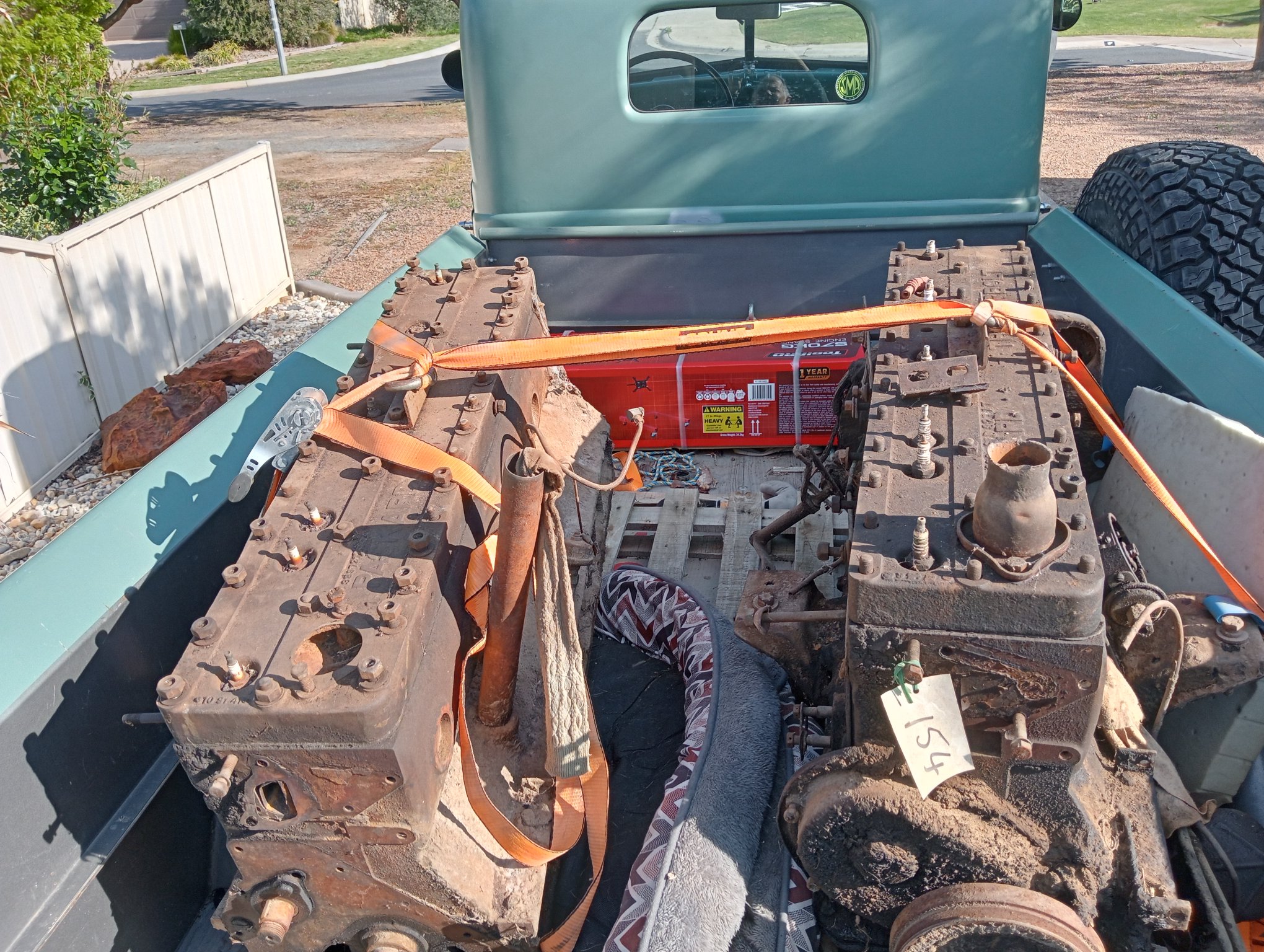
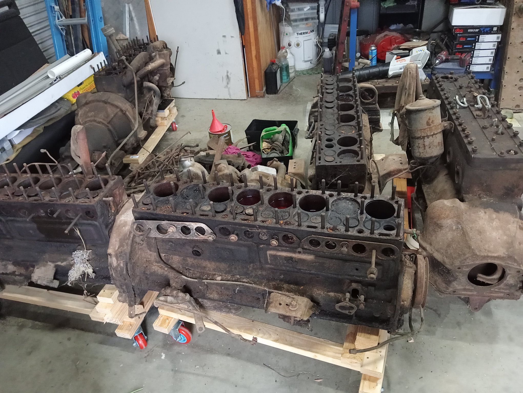
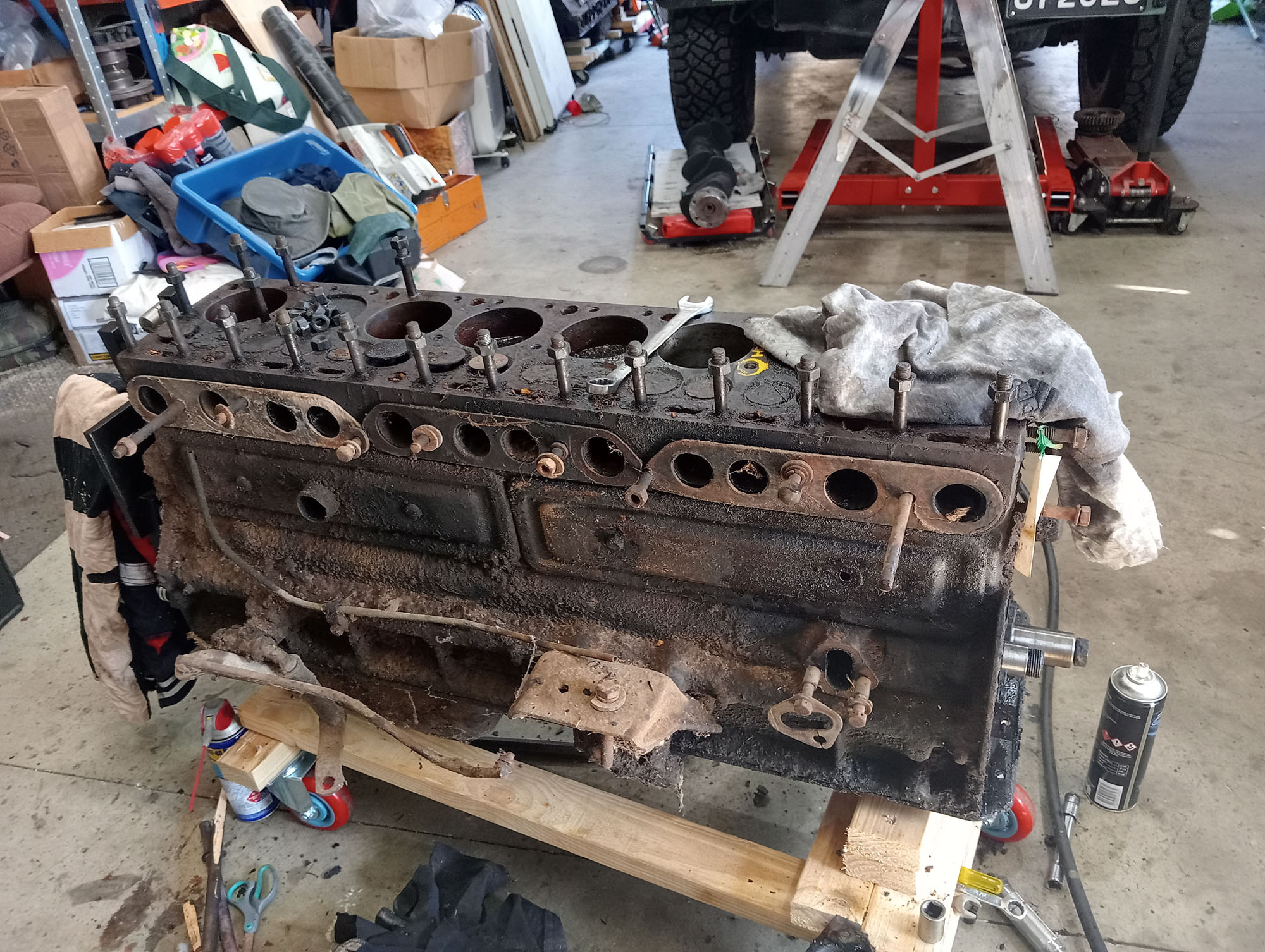
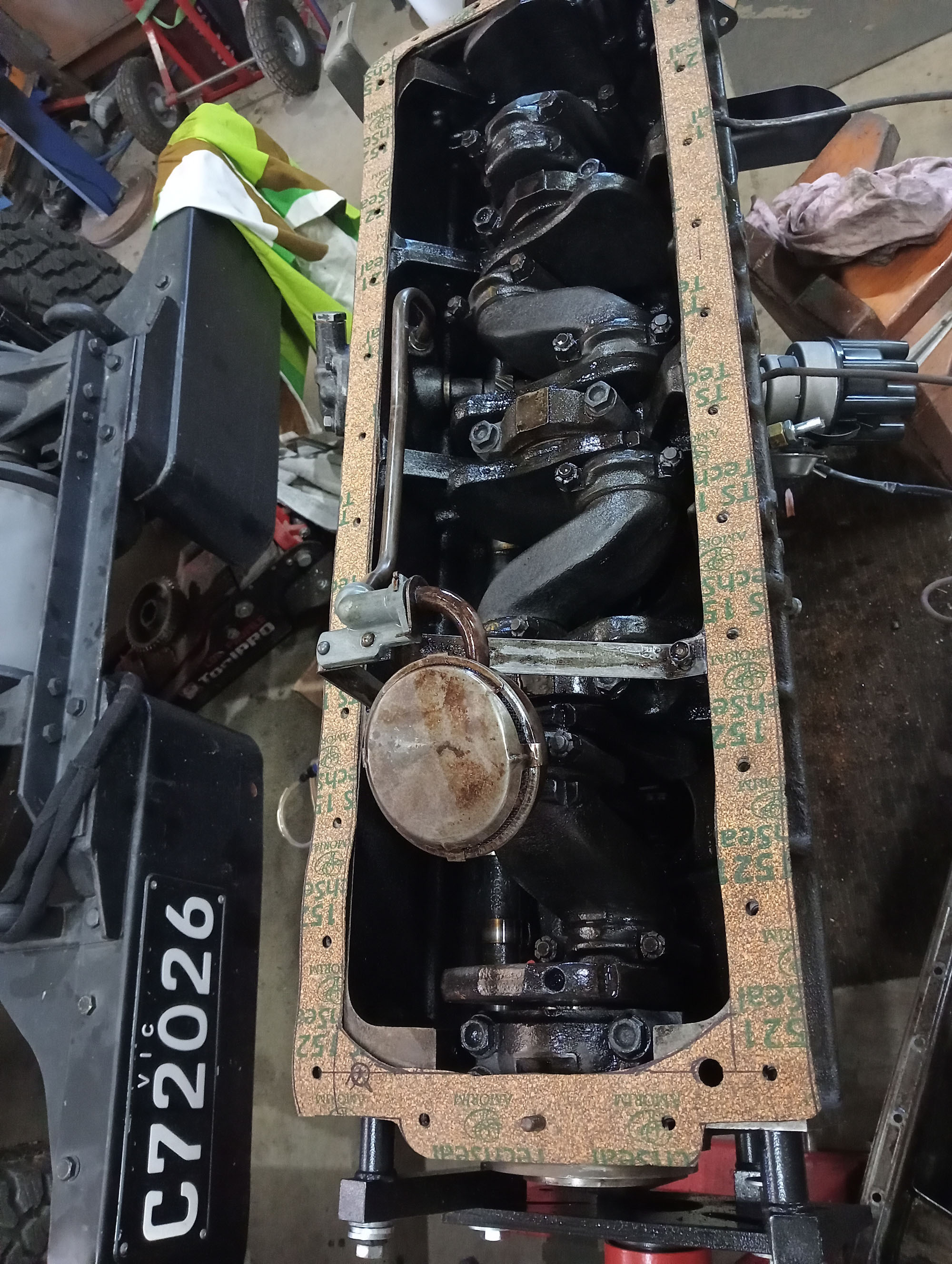
I touched on the Engine earlier in this page, basically I bought 5 x unknown condition, incomplete, Packard 'straight eight' engines, Luckily they are all the same series 288 cu inch so parts between them should be interchangeable. Unluckily all the engines are seized solid. Two engines had been canabalised and were missing some pistons & rods. I was able to free up & dismantle 4 engines & chose the best of the parts to build one engine.
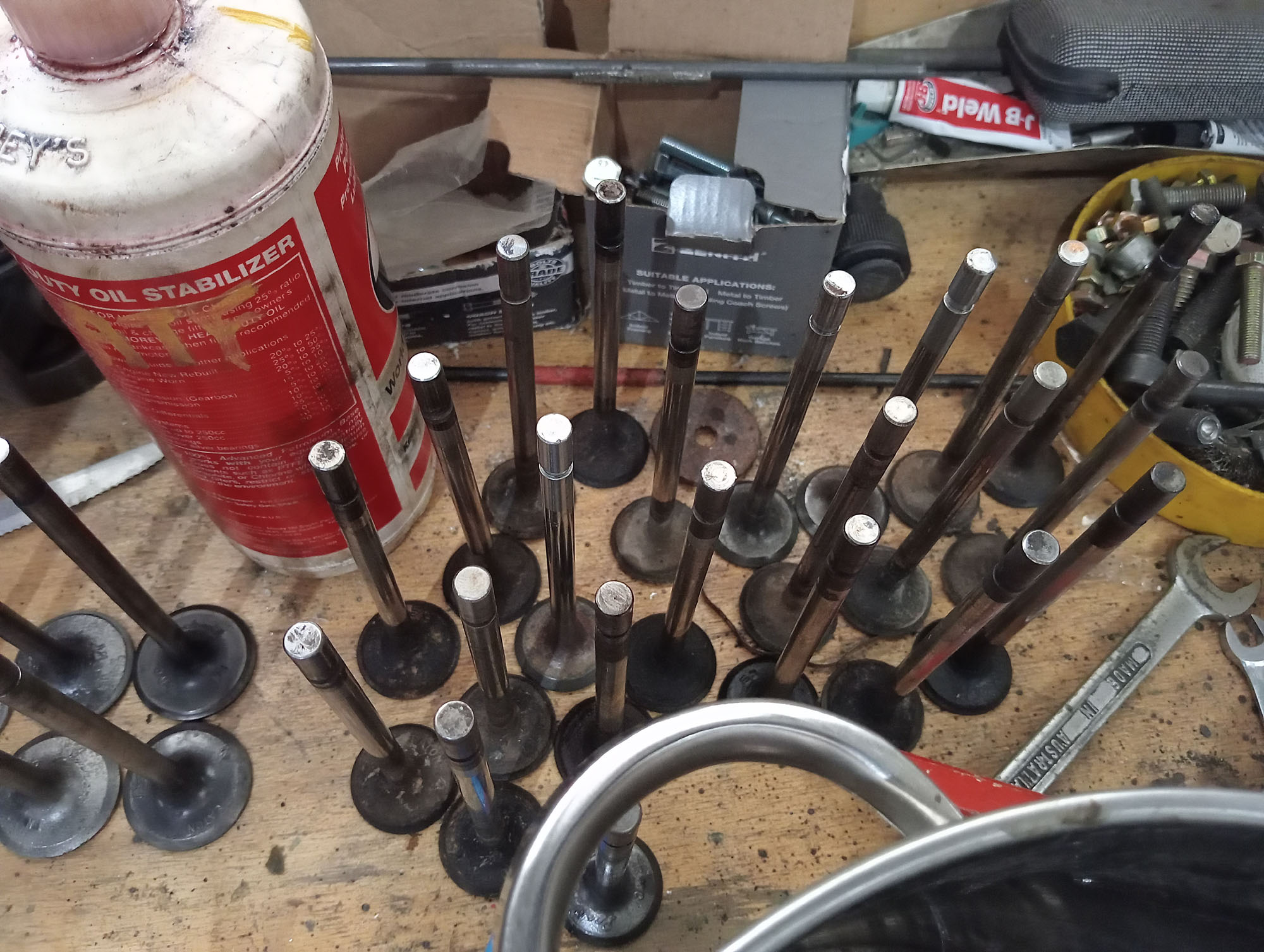
To make one good running engine I needed one good block, one good crankshaft, 8 pistons & conrods, A good set of bigend & main bearings, Camshaft . lifters, Inlet & exhaust Valves & springs and one good cylinder head, Oil pump , Sump etc. etc. .
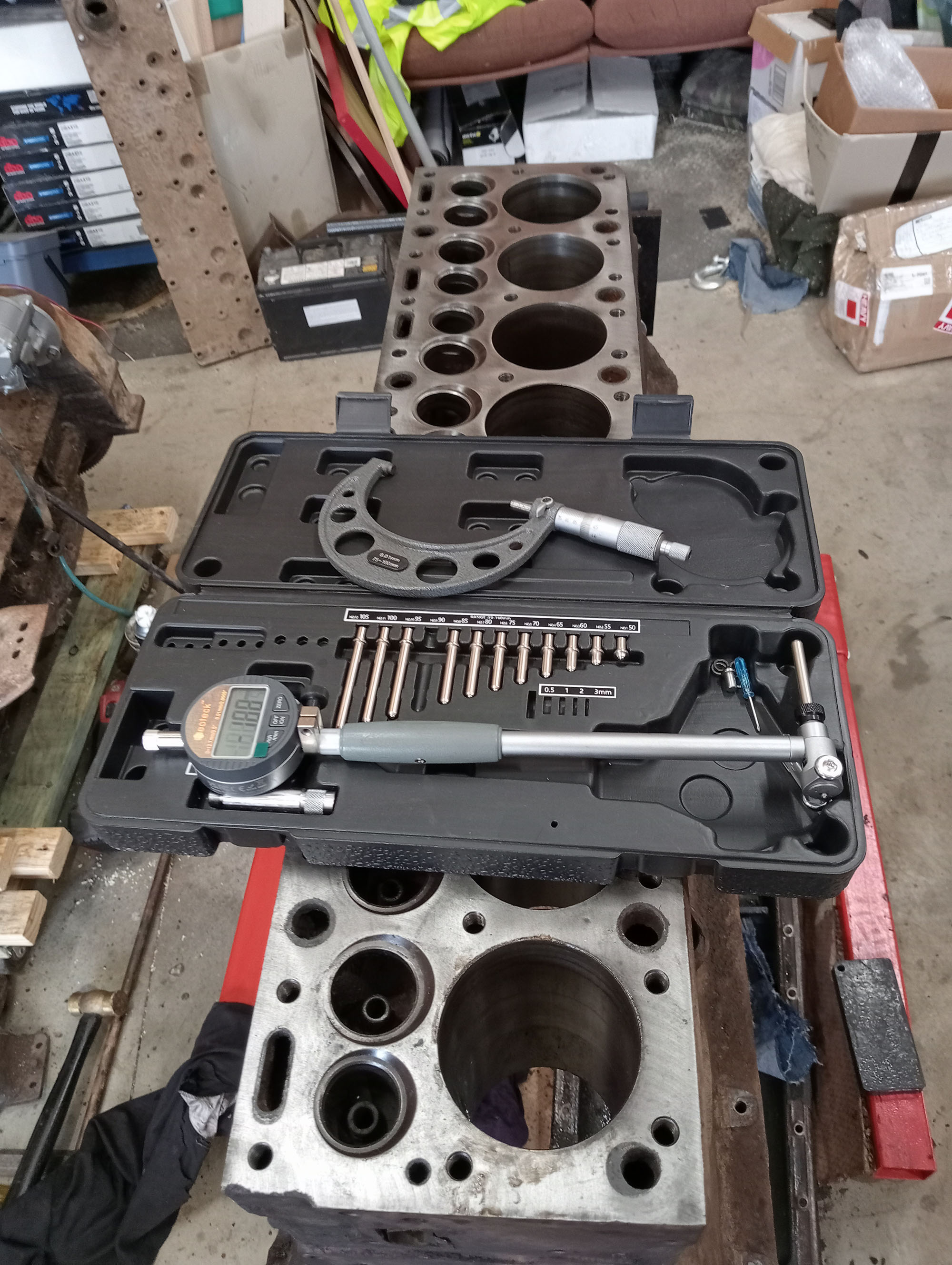
Obviously the best way to build any engine and expect great results is with a Rebore, crank grind, new oversize pistons & undersize bearings, which are available (and very expensive) ex USA, but for the purposes of this build a running engine is all thats necessary. A DIY Cylinder hone, crank polish & fresh piston rings & timing chain will suffice & new head gasket should be the bare minimum that's required.
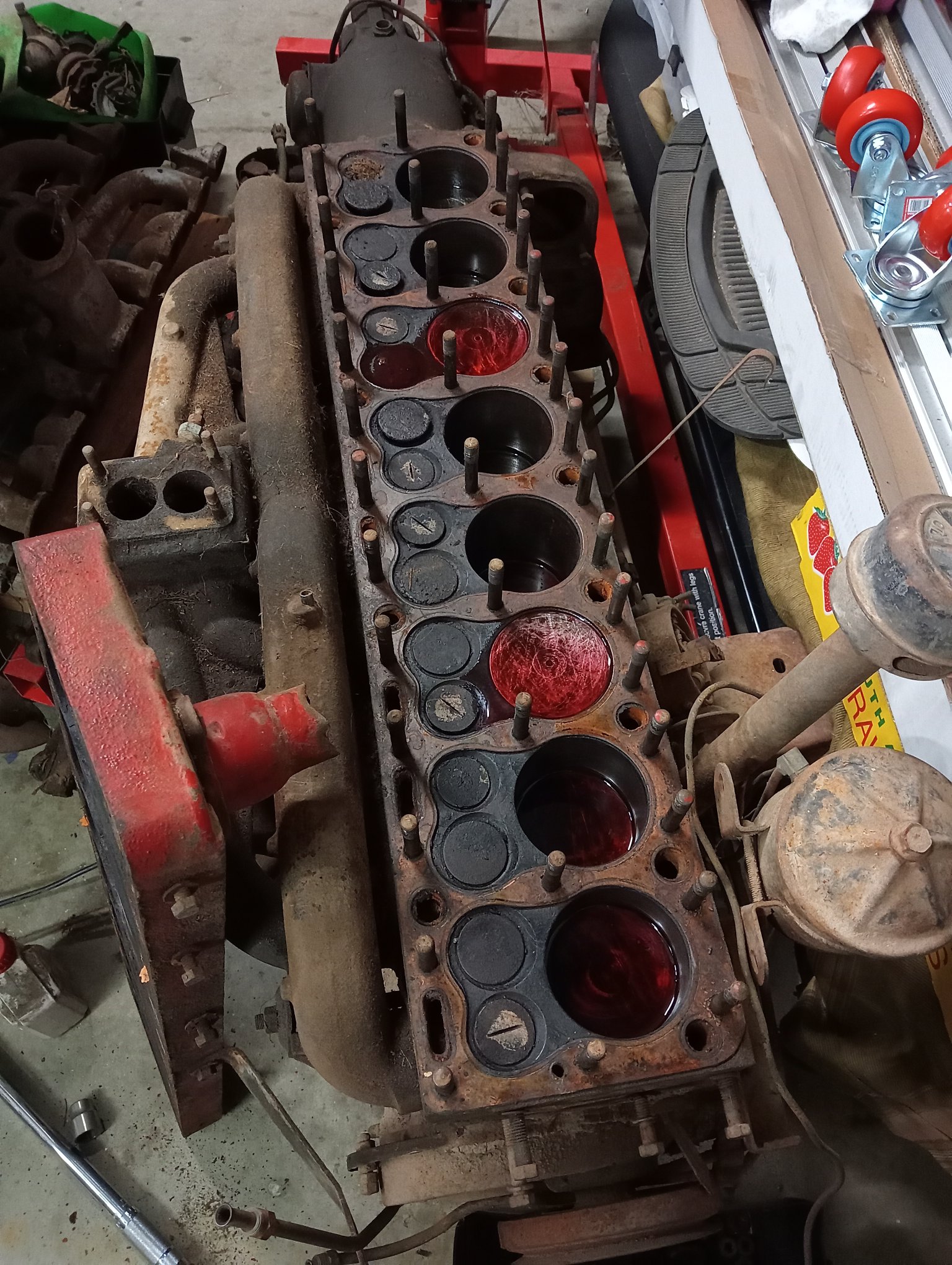
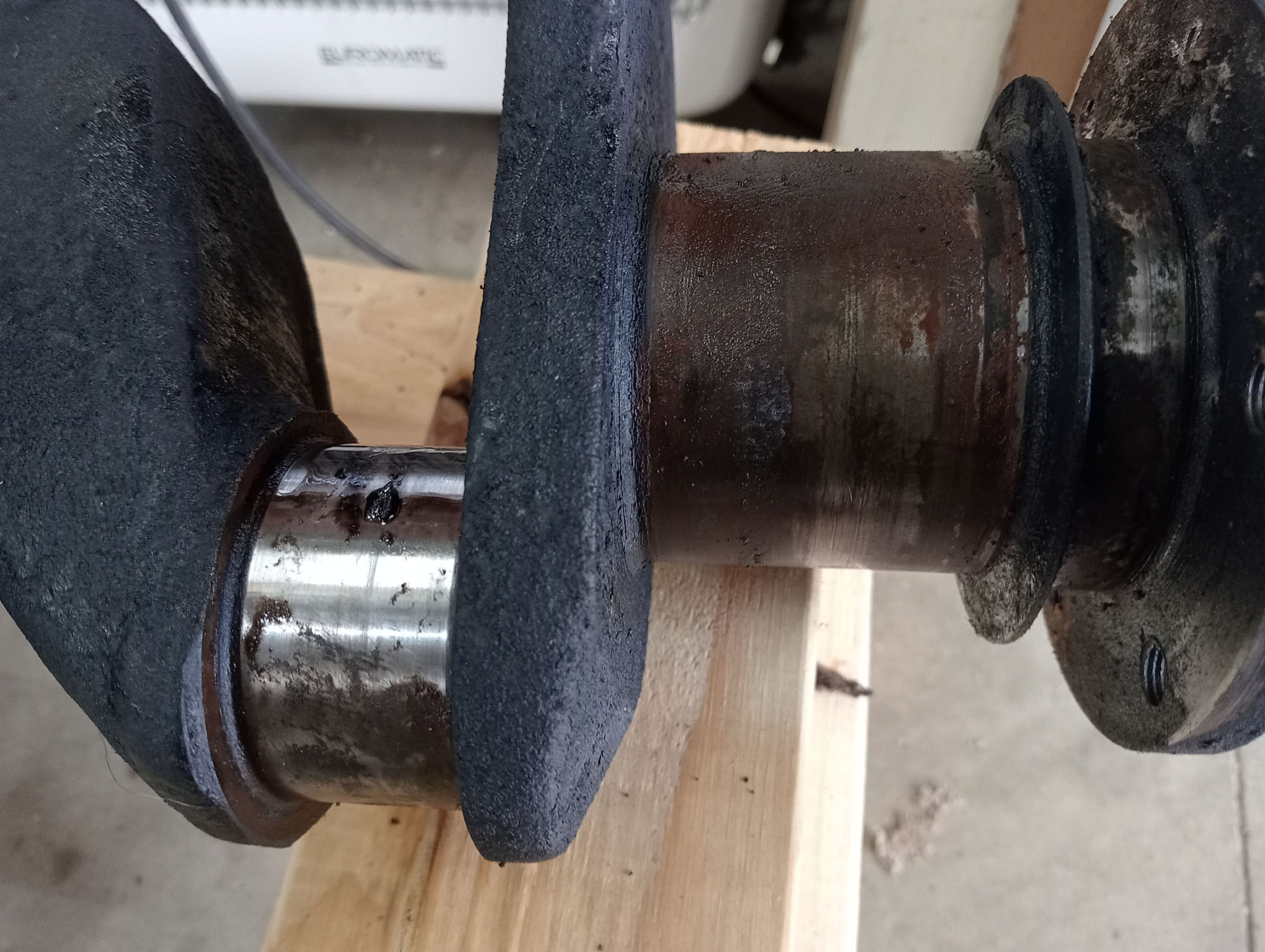
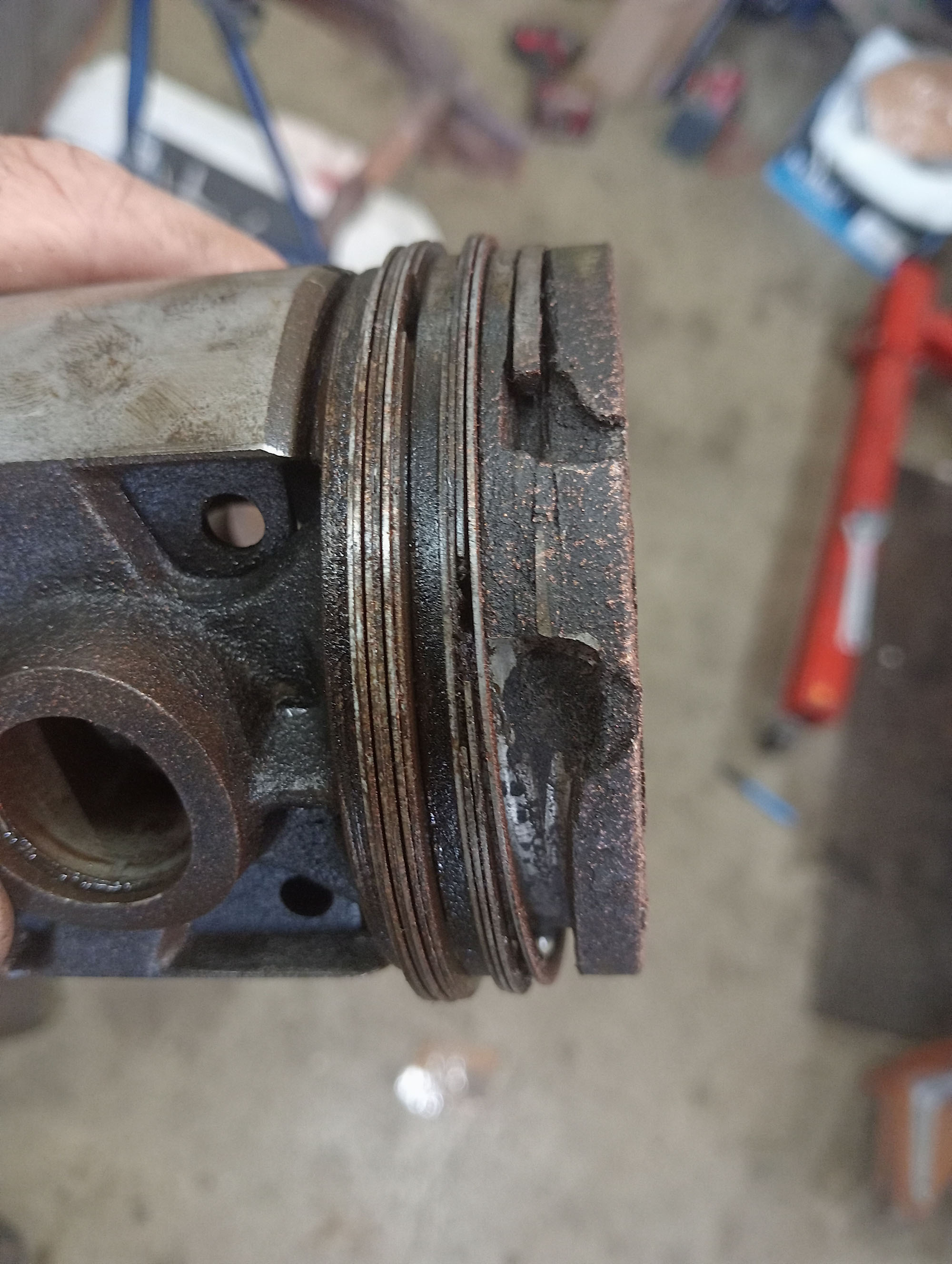
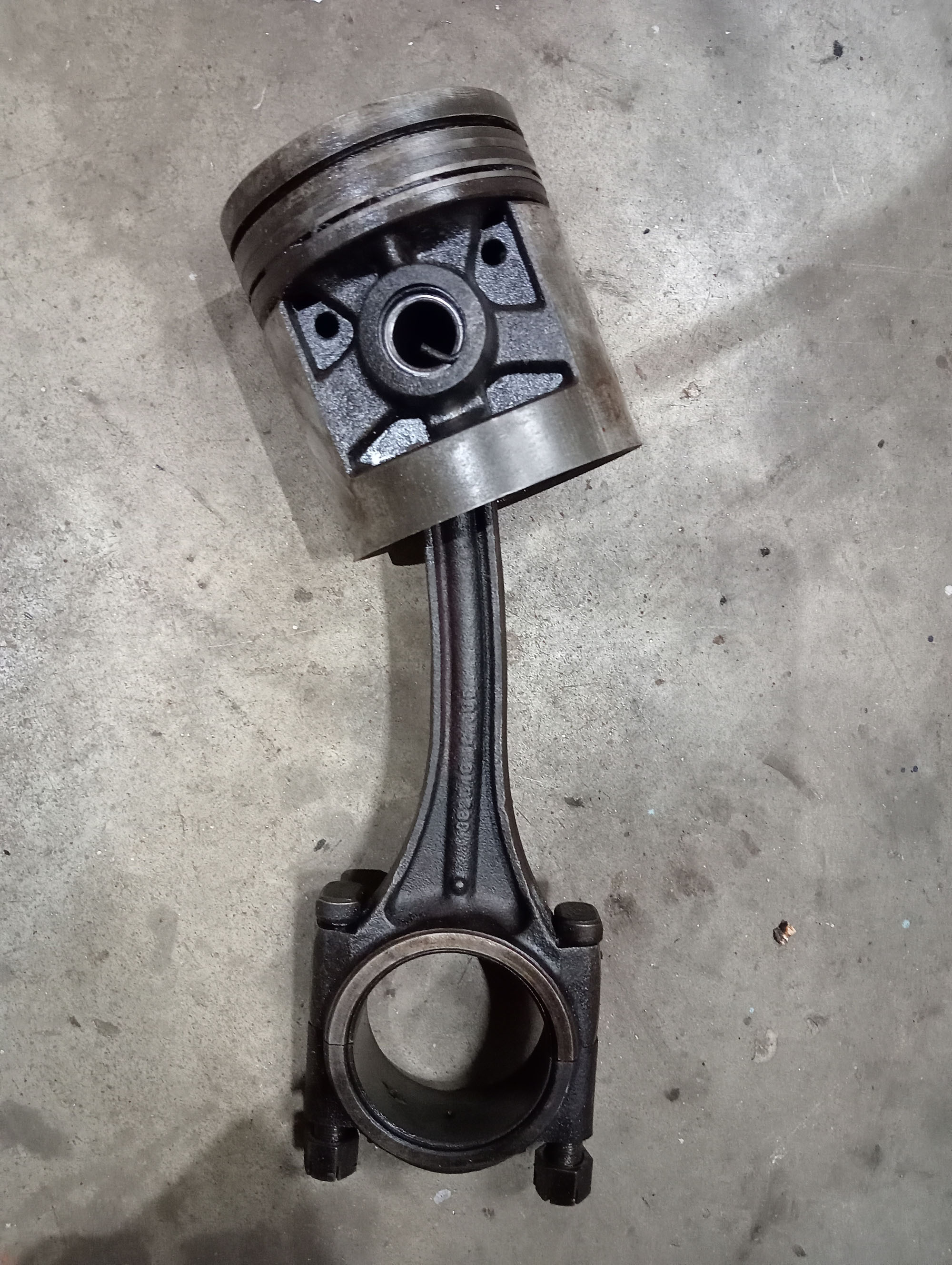
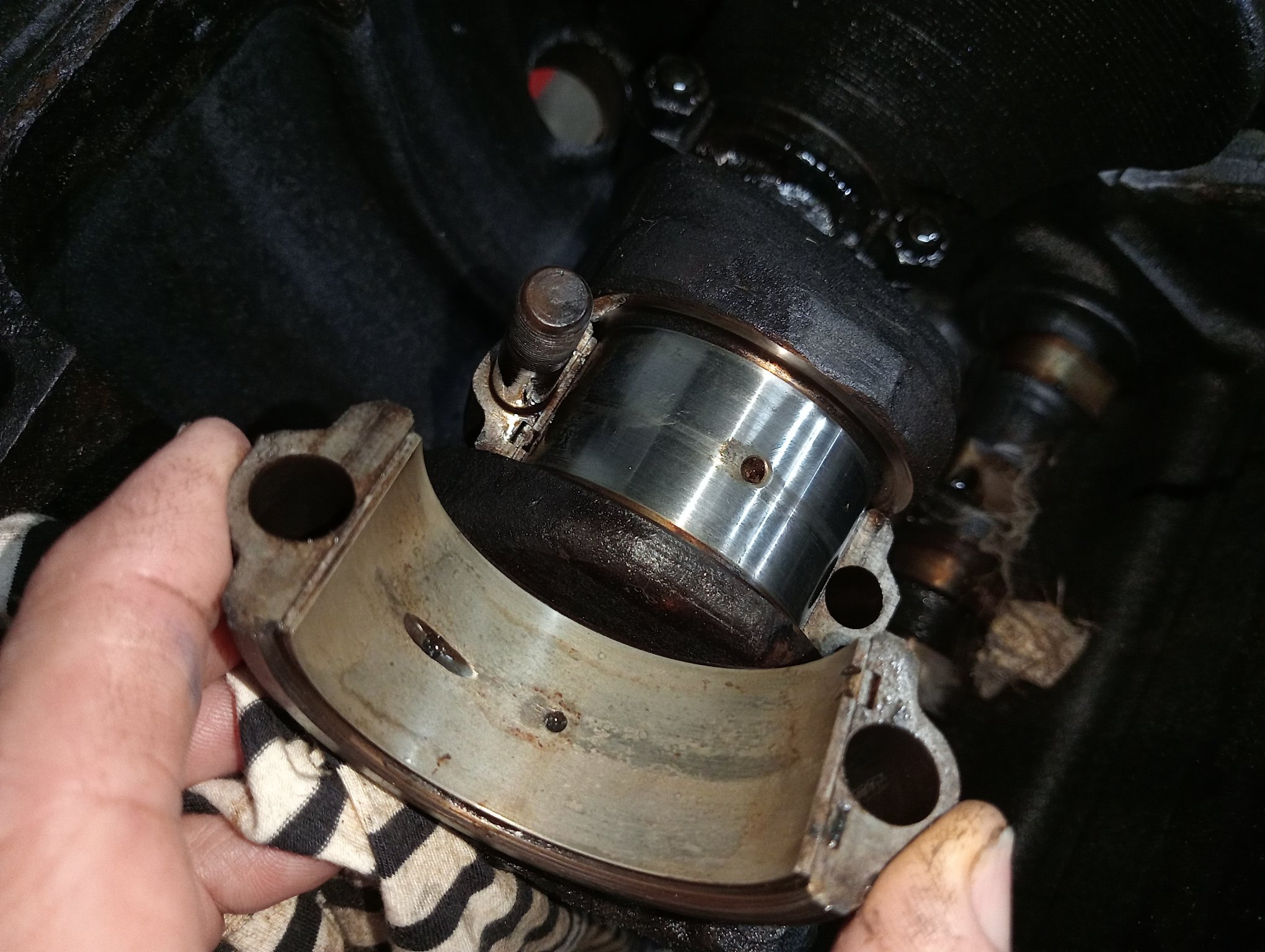
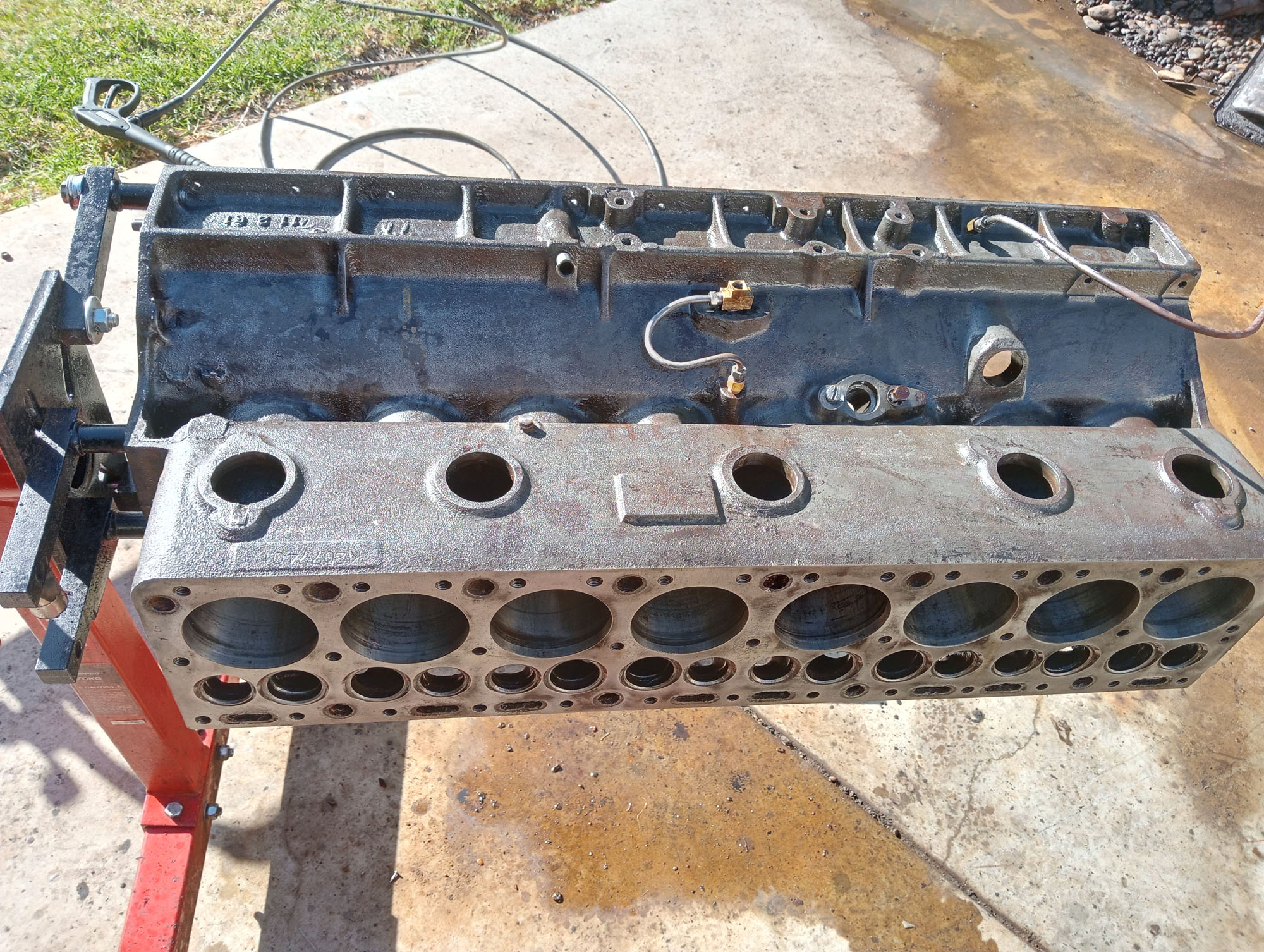
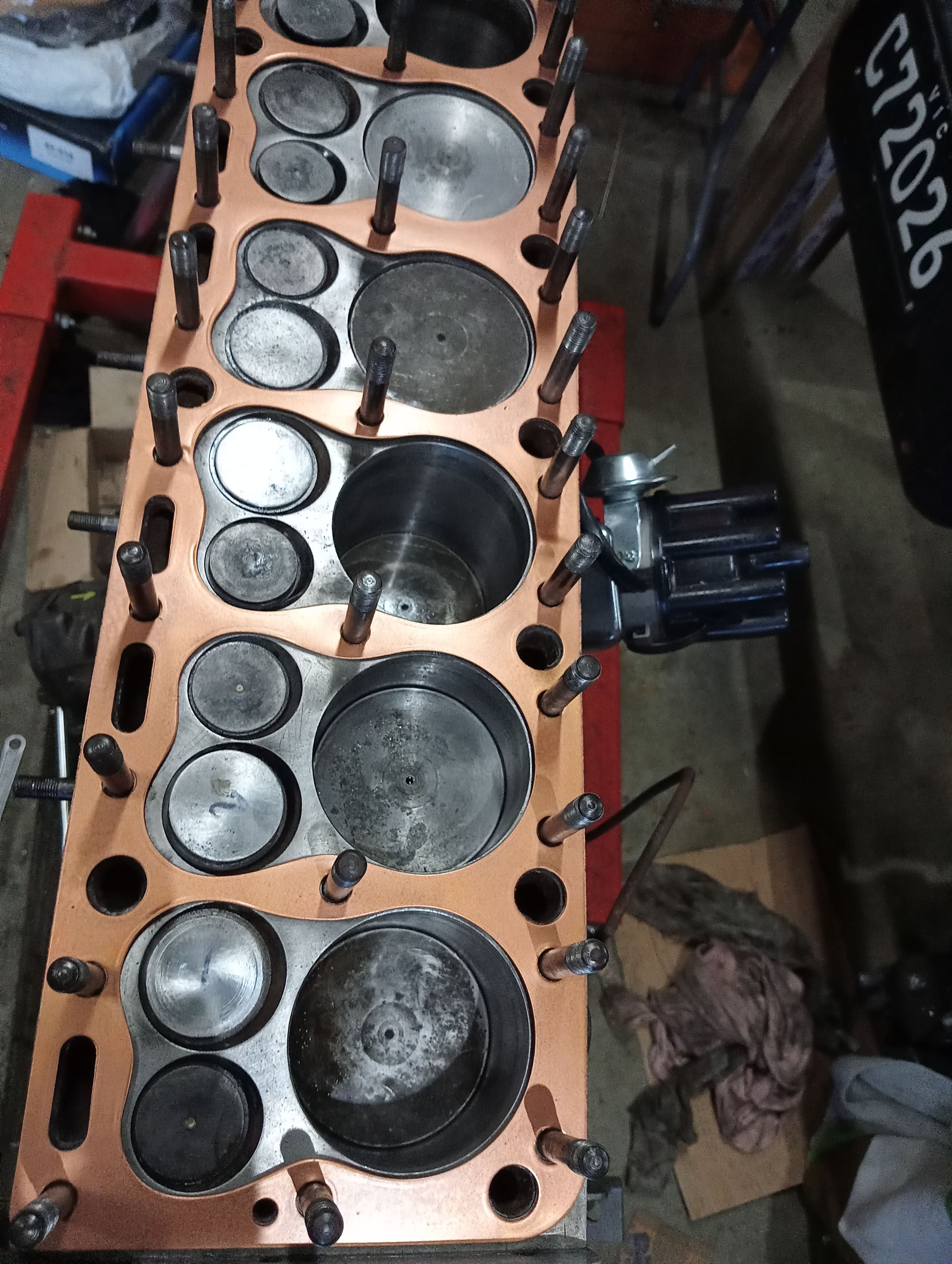
For the most part the insides of the engines were very good for their age, All bores and pistons were standard at 3.50" bore, And all crankshaft journals & bearings were original. There was environmental damage (rust) . The rear main journals on 3 engines were rusty & need regrind - One crank was good. One Con rod was bent and some pistons were in really bad condition.
Below are photos of the worst of it.
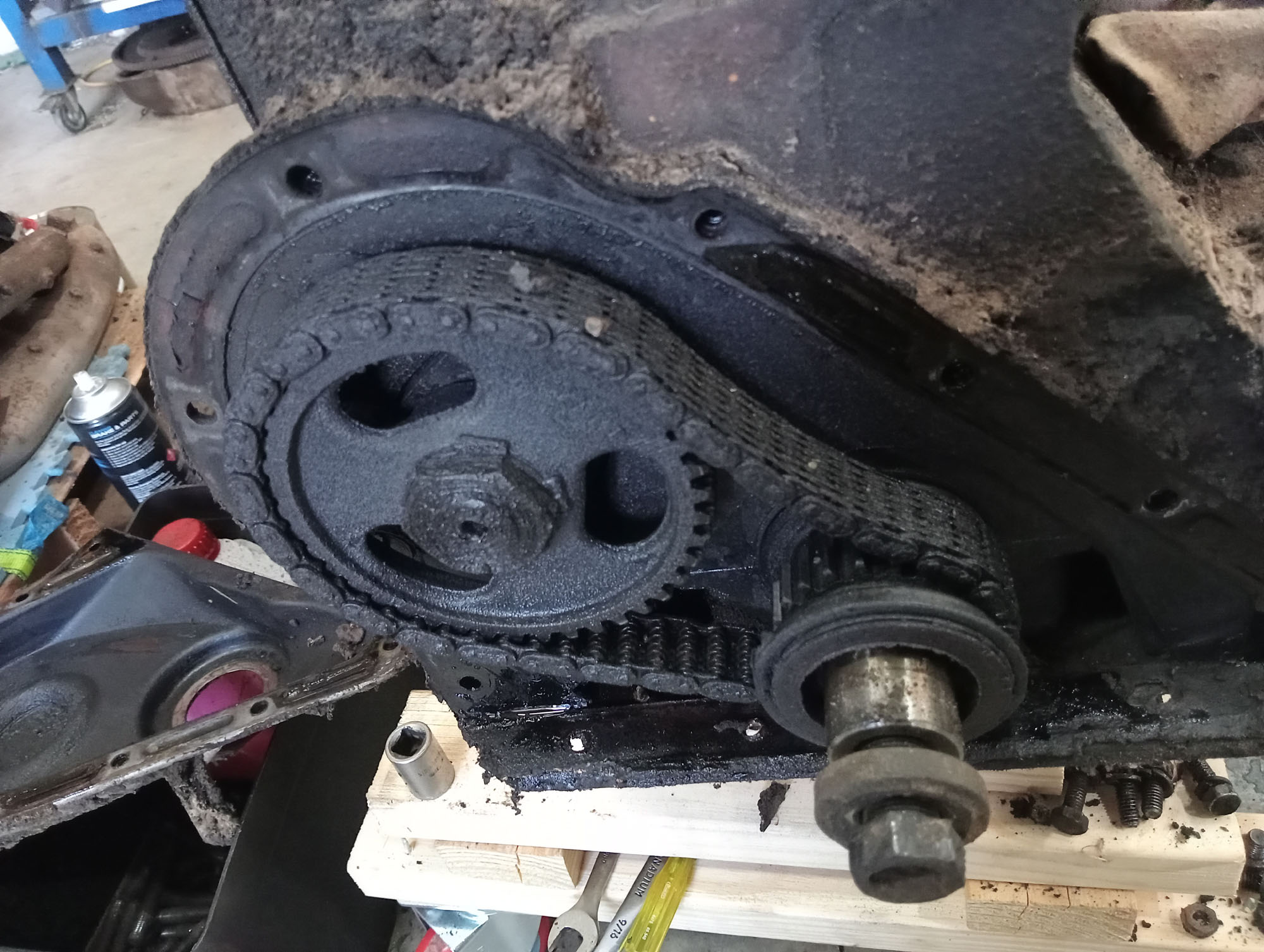
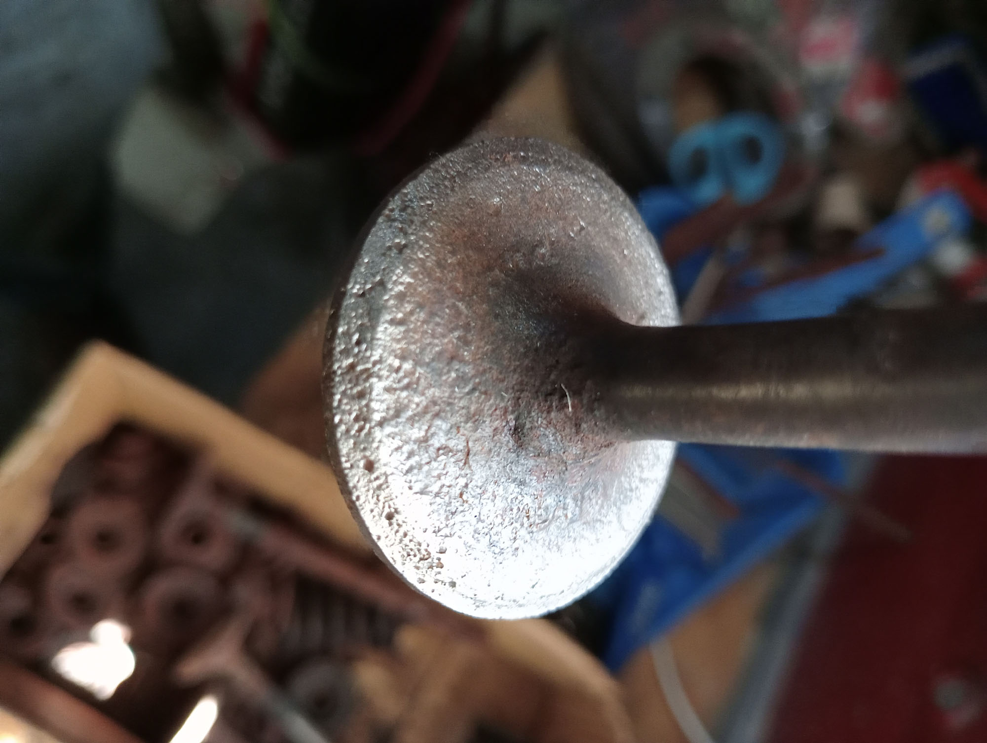
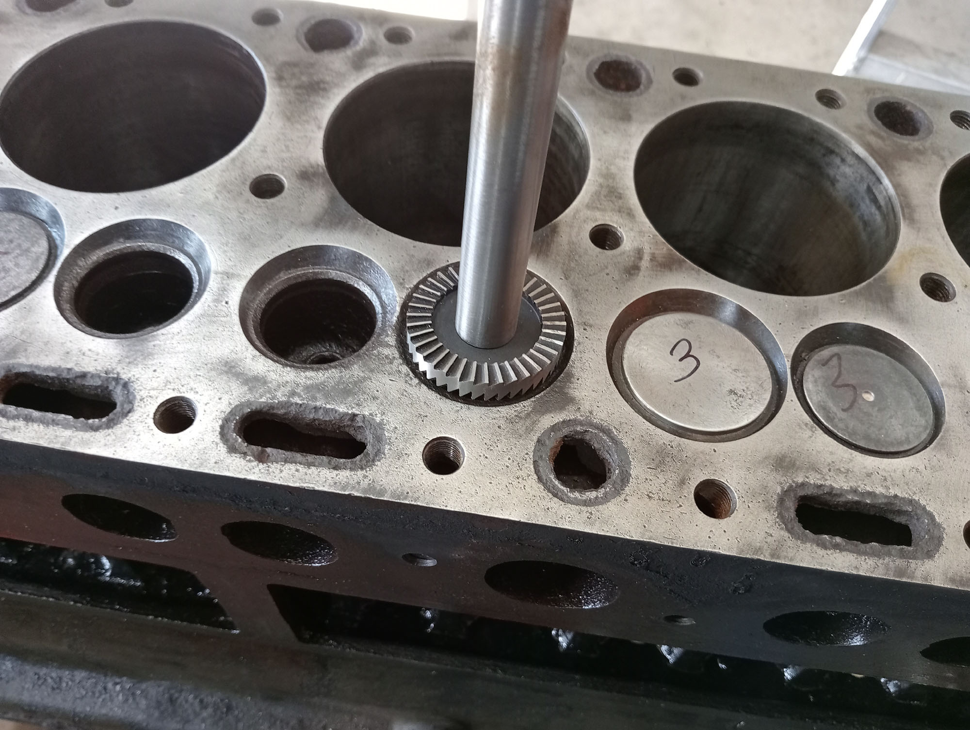
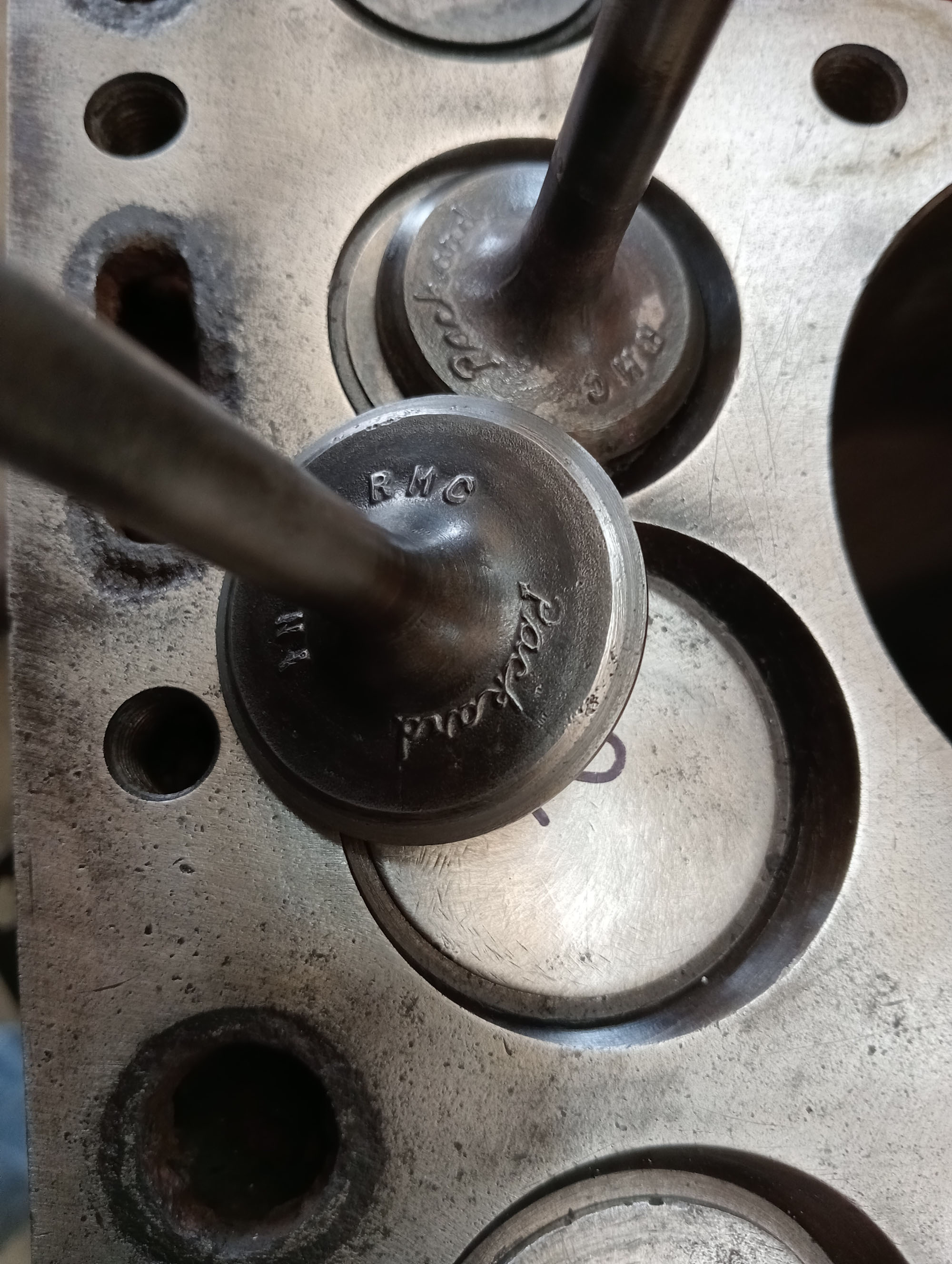
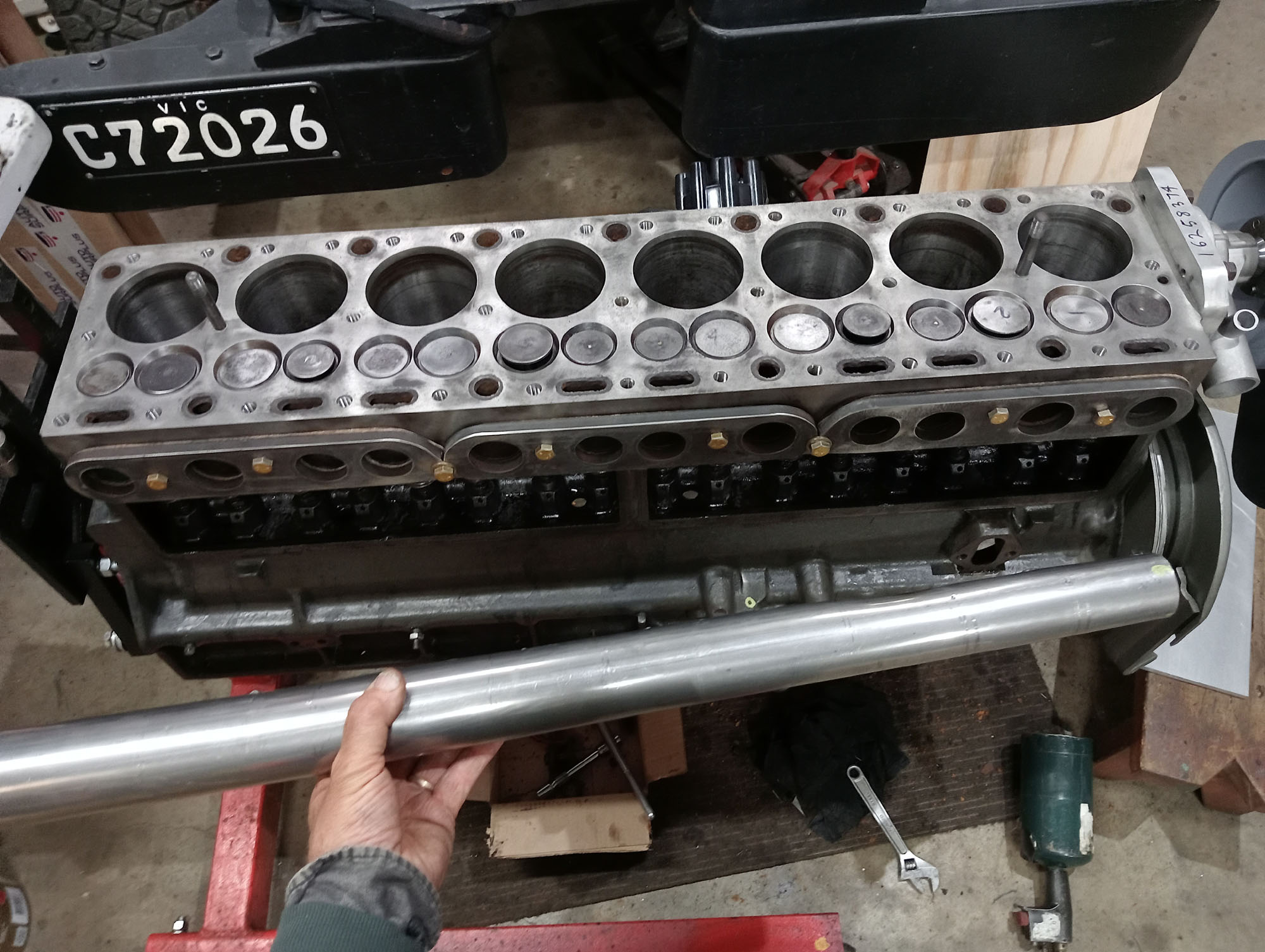
Below are photos of stripping, cleaning and reassembling the engine that I determined to have the most potential to rebuild without machine work. I did need to remove the top ridges & hone the cylinders, After honing the piston to wall clearance was between 7-10 thou, that's well worn, about double a fresh engine which should be about 3 thousandths of an inch.
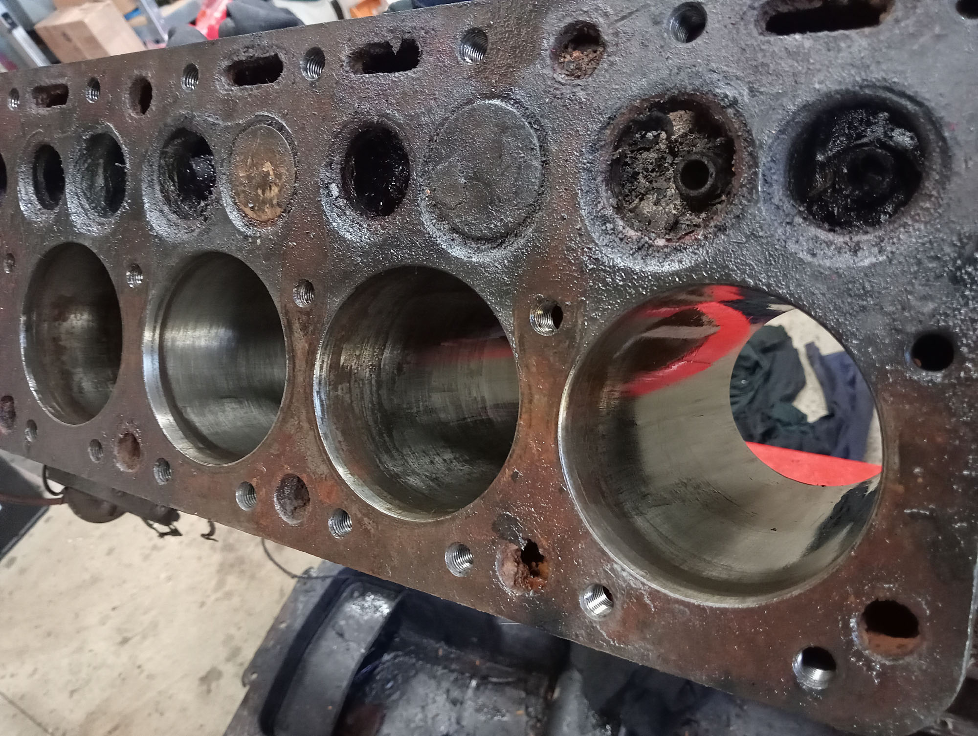
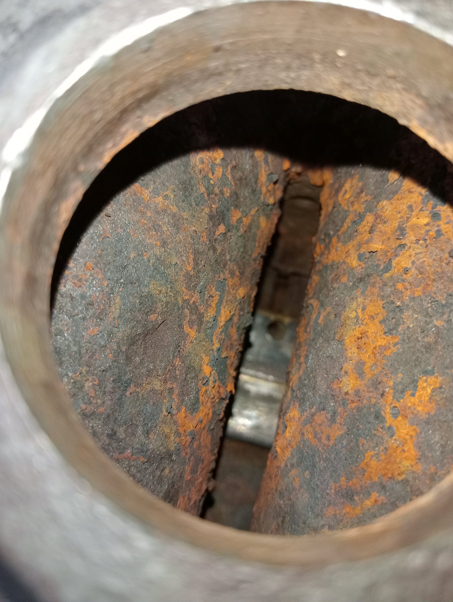
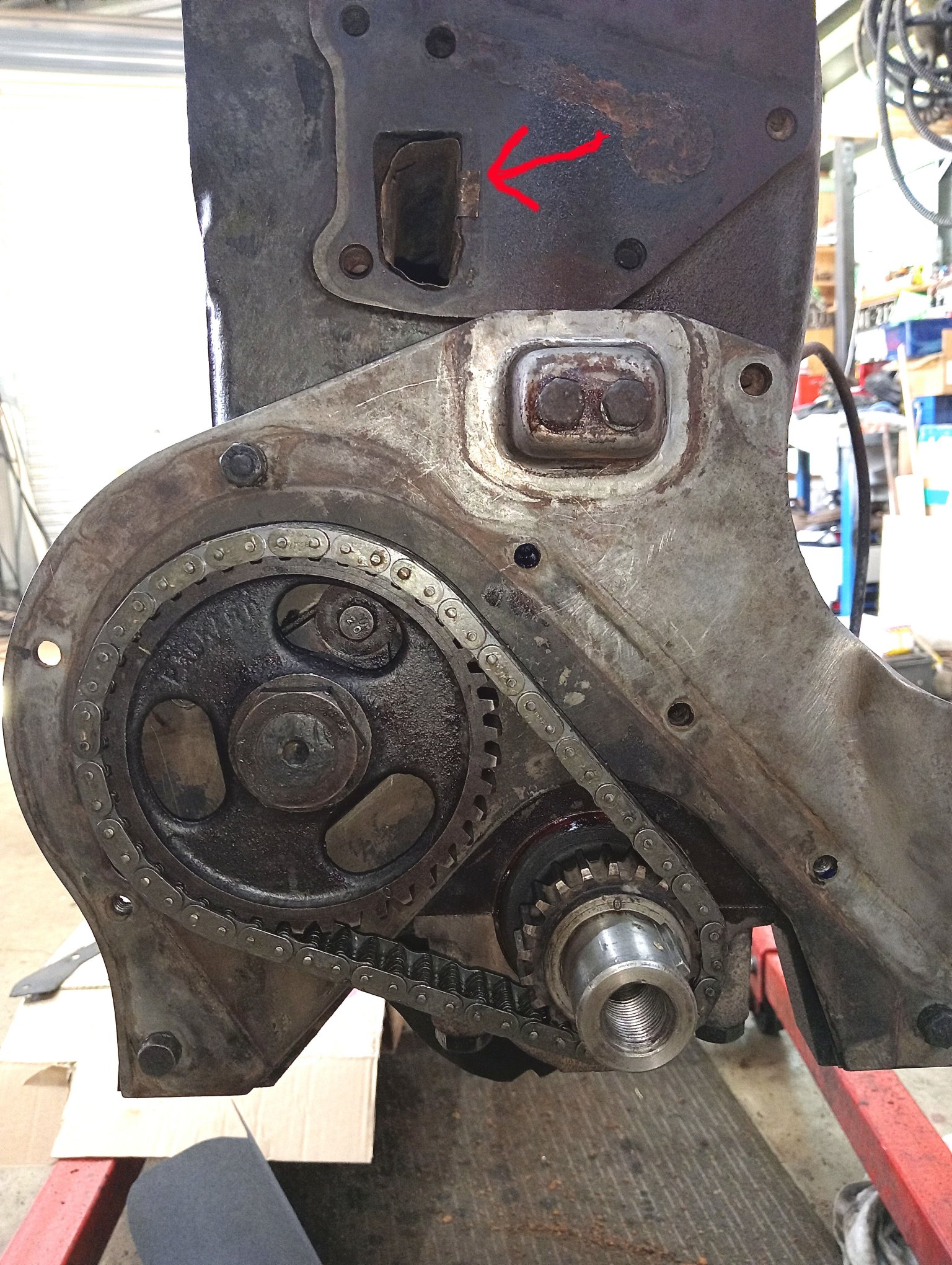
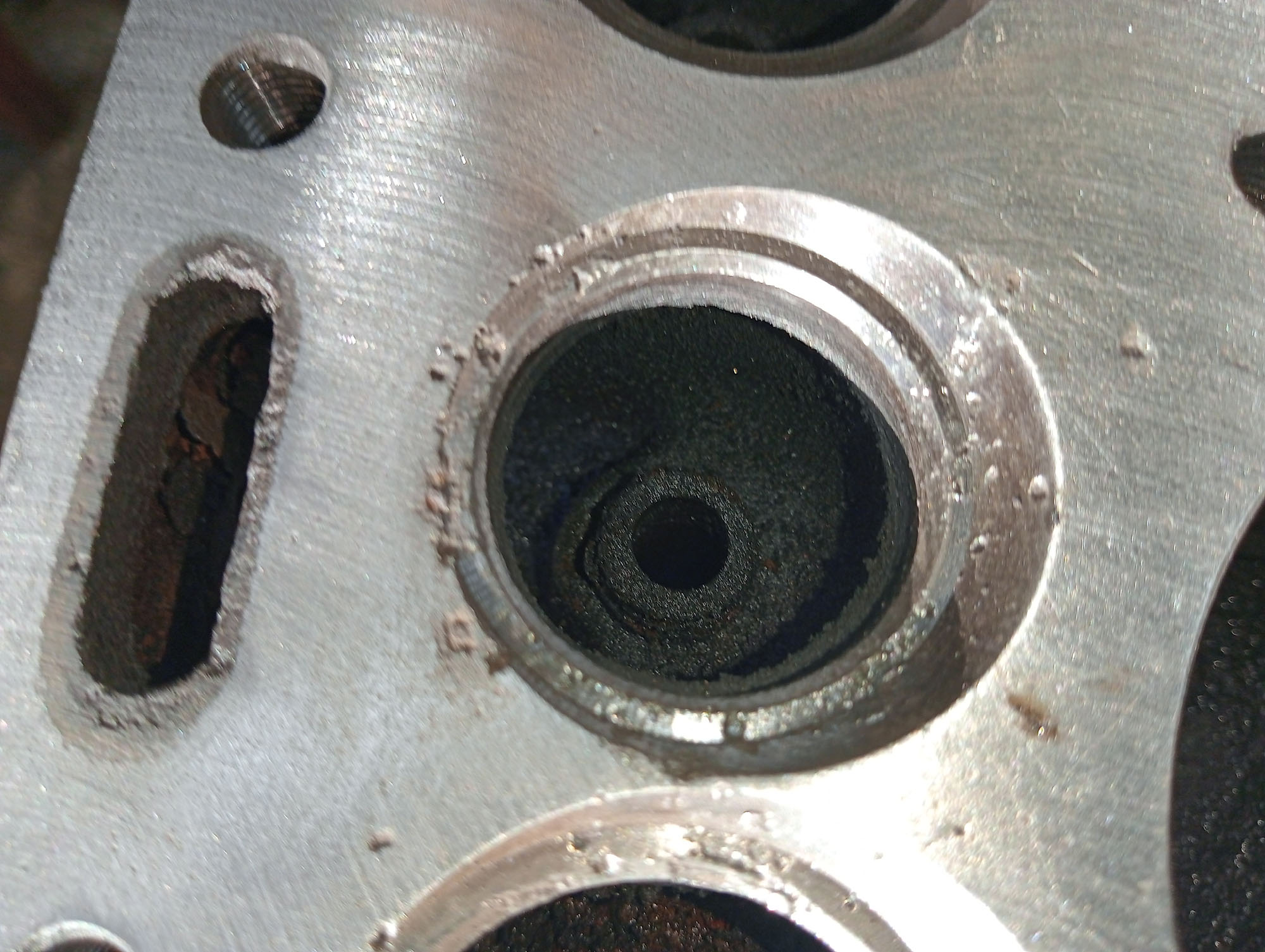
The first photo at left is taken looking inside a welch plug hole. The engine is completely free of rust and scale, to the rear the brass water distribution tube is visible. This directs water from the water pump onto the exhaust valve seats before distributing it around the rest of the engine .
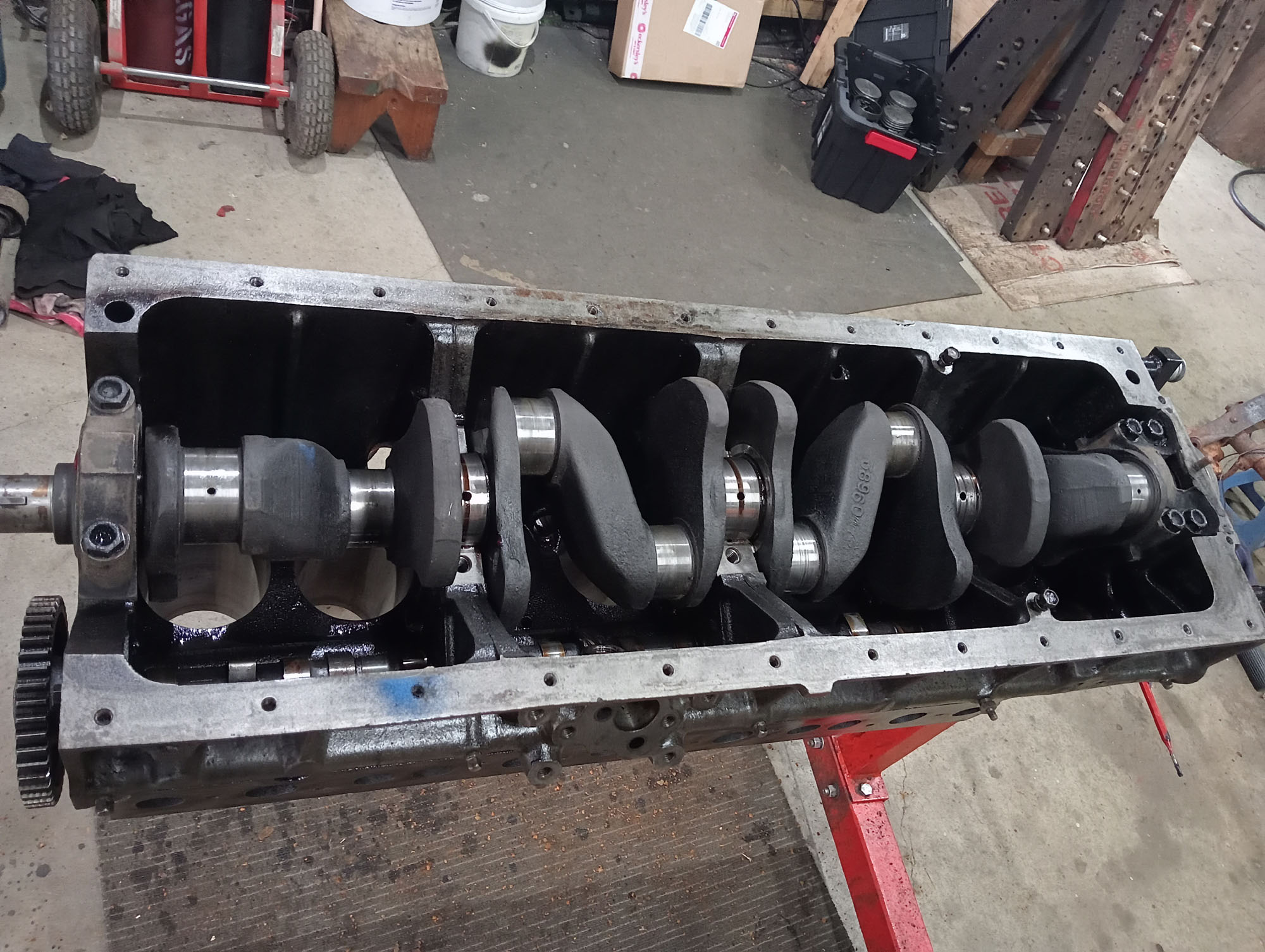
In the next photo an arrow points to the front of the distribution tube. The tube runs all the way along the engine. Also note the new timing chain.
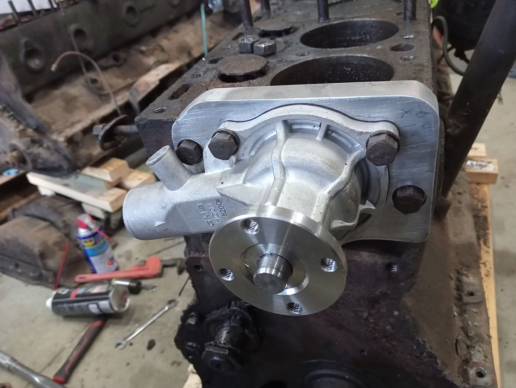
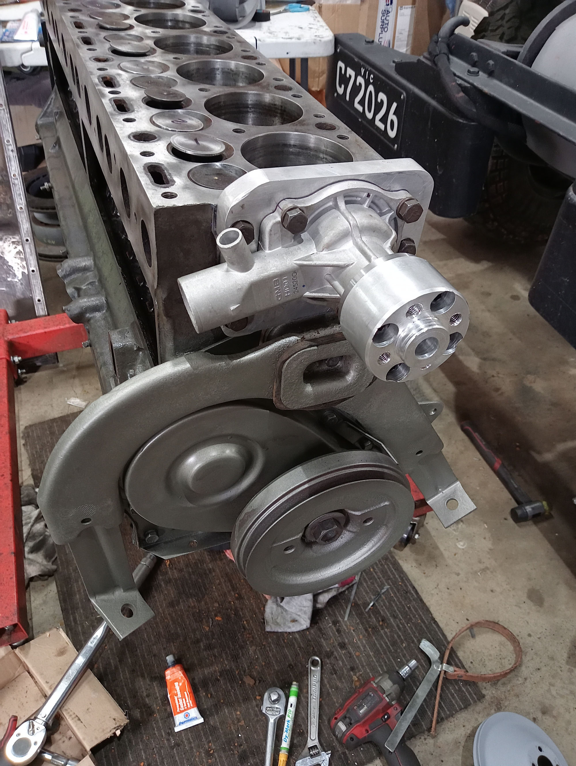
Water Pump
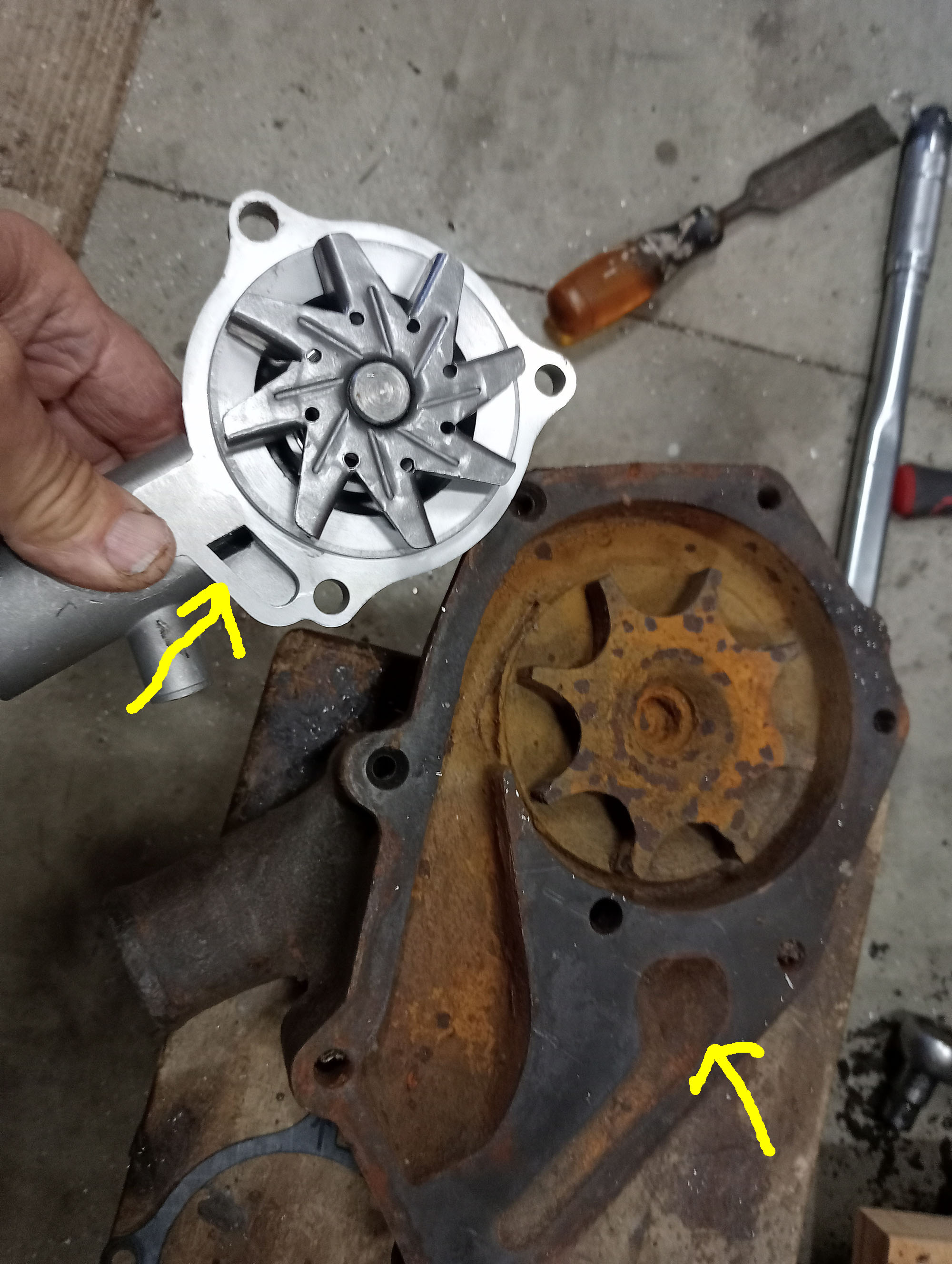
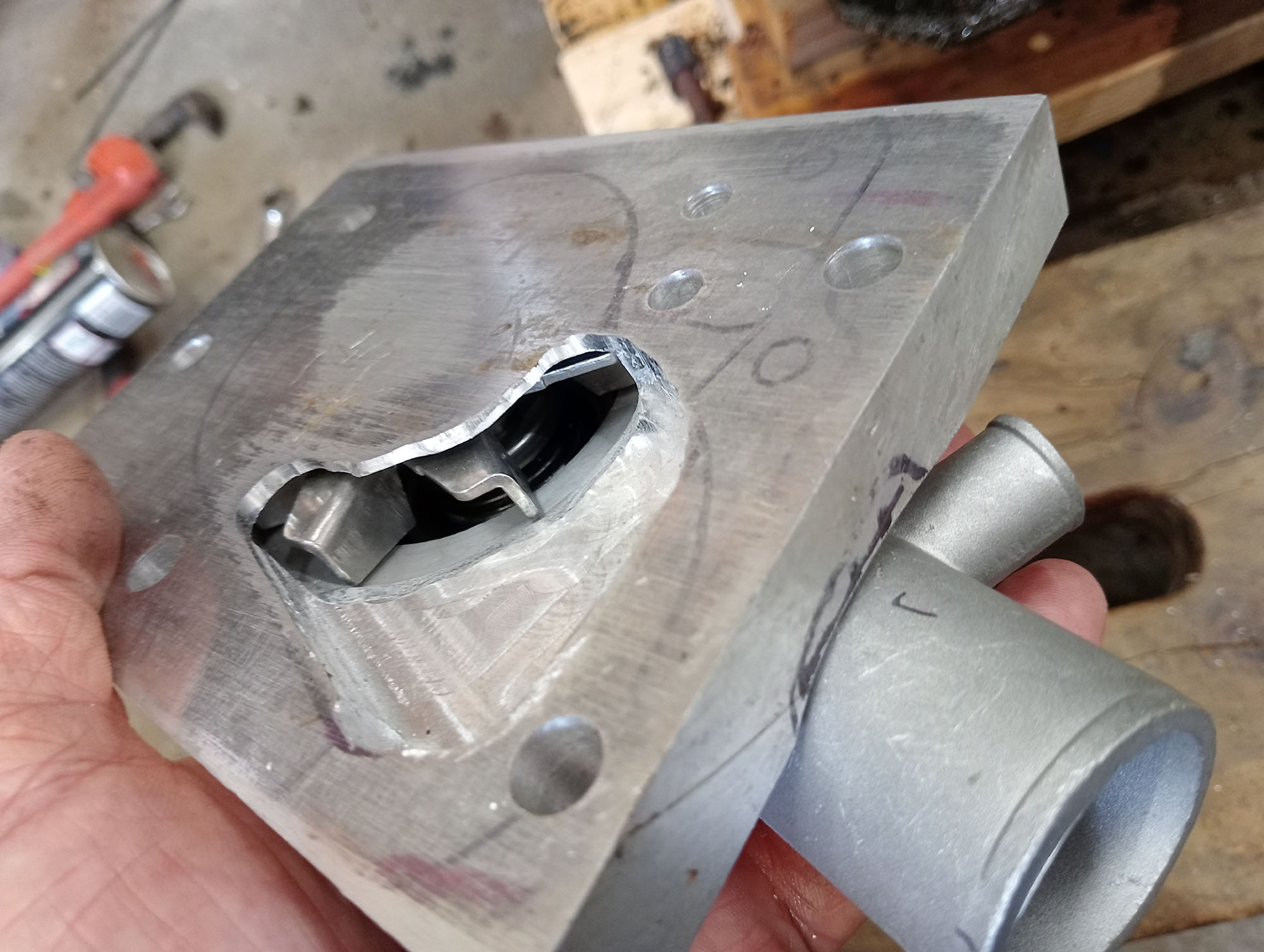
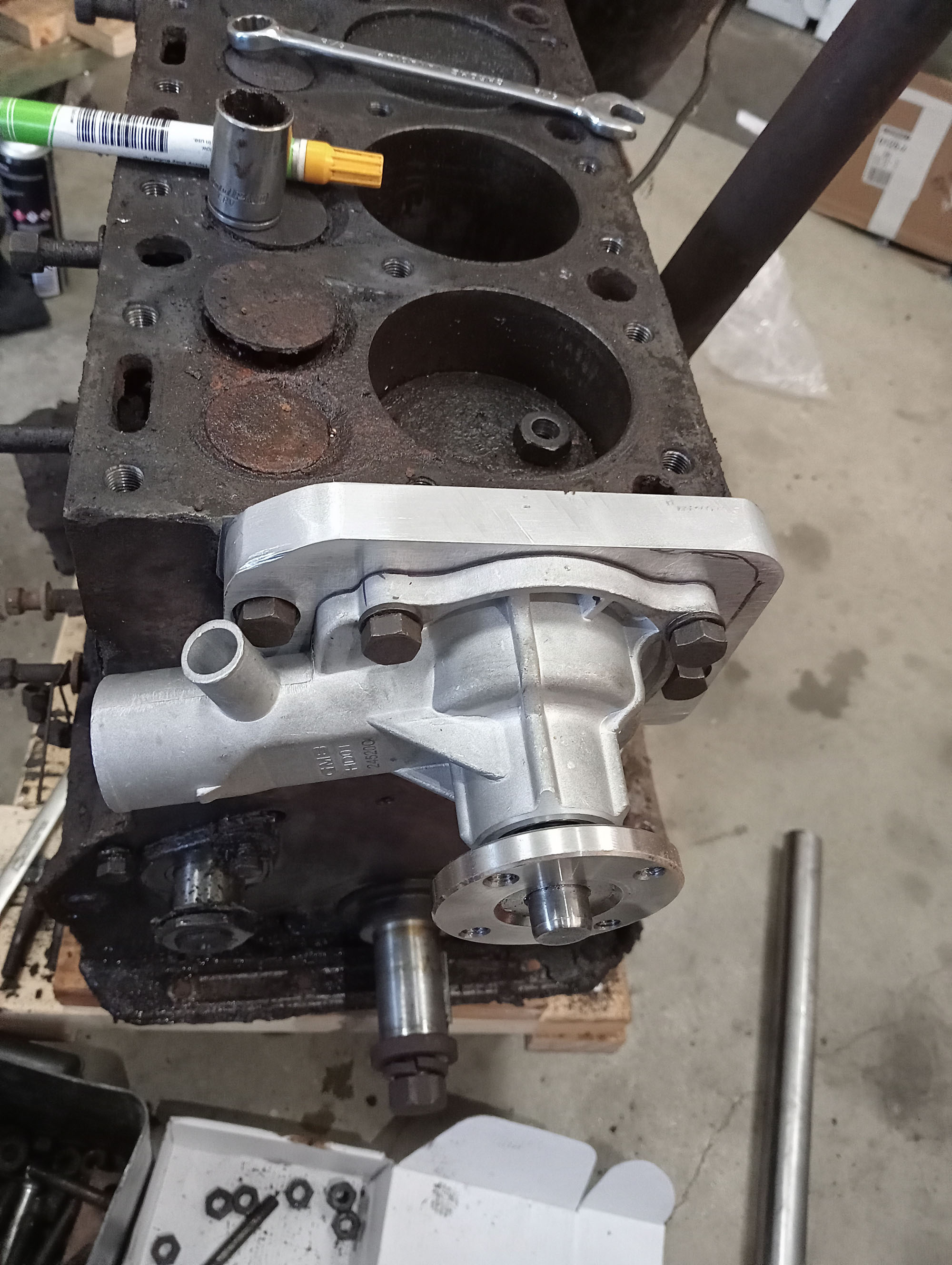
One water pump came with my engines, Its a Later 200 series pump positioned for lower / wider radiators so the pump is in the wrong position for my upright radiator . Of course I could a correct repro pump from the US of A but I had a red motor pump here so thought I'd see how it compares to the Packard pump.
Impeller & input pipe are the same size , and bypass port wont be hard to line up. So why pay $500 when a $50 pump will work. (arrow points to bypass port)
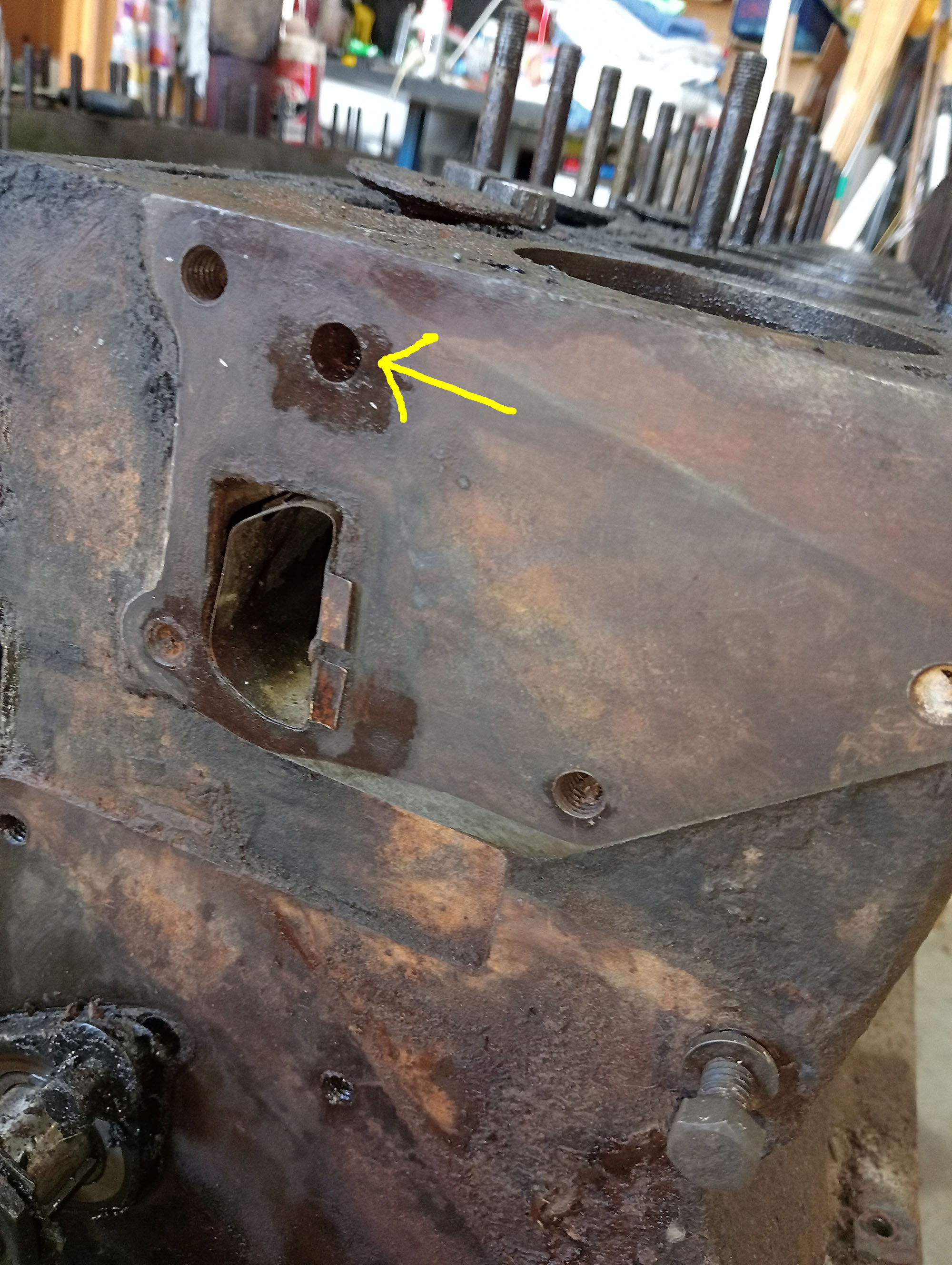
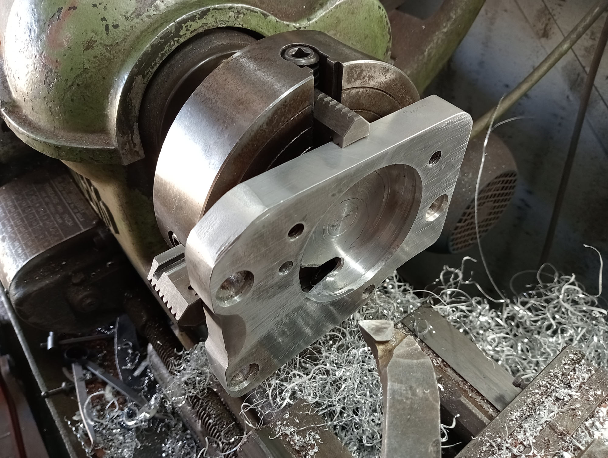
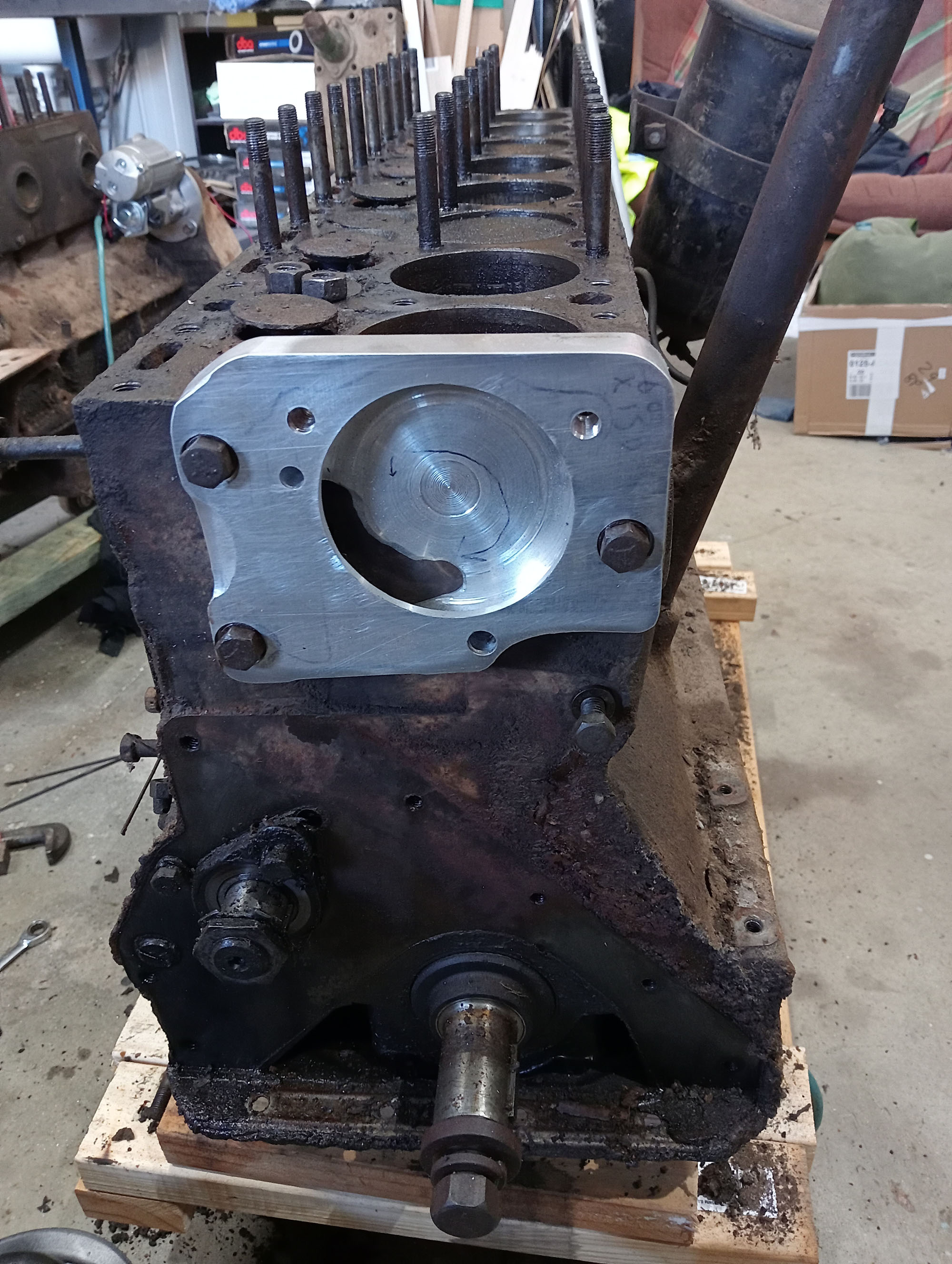
Photo at right shows the front of block with the water distribution tube where the pump sends all the coolant. The arrow points to bypass port, The bypass port allows flow of water around the engine during warm up before the thermostat has opened.
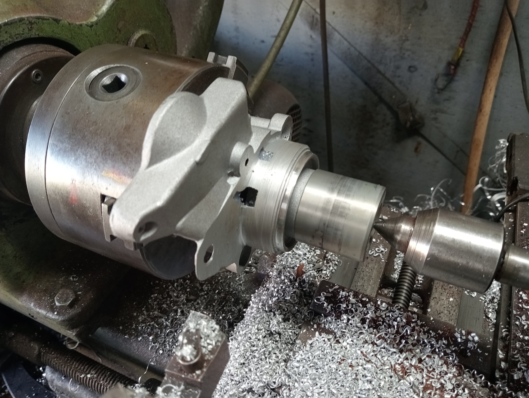
Distributor
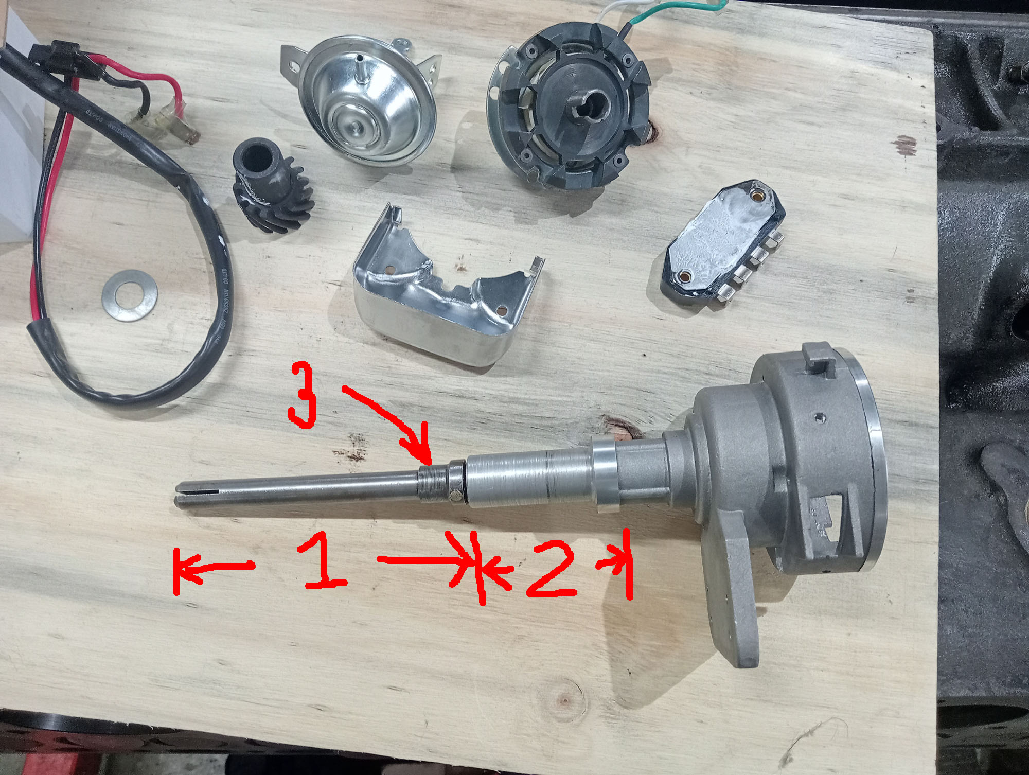
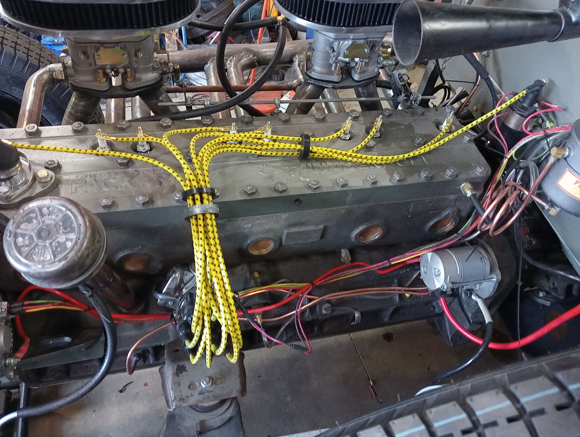
My engines came with a few distributors, none complete, and knowing how hard (and expensive) it is to find points, rotors & caps for these I decided to see if I could fit a modern HEI distributor. The advantages of a Bosch HEI system is a better longer duration spark, & full intensity spark at cranking speed, even with on a cold day with a flagging battery, so no need for a ballast circuit. no points to replace and adjust and of course common distributor caps.
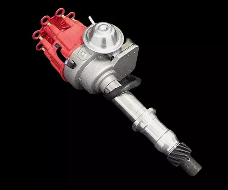
A V-8 distributor will work in a straight 8, The Packard distributor rotates anti clockwise, so the replacement must be an anti clockwise unit, the difference is in the centrifugal and vacuum advance mechanisms, the wrong rotation direction would retard the timing , instead of advance.
Anti clockwise distributors are used in Pontiac 287-400 SB 421-455 BB so I bought a Pontiac Bosch style HEI distributor for $89.00, Not a huge investment to kiss goodbye to if my idea didn't work. Ford Windsor or Cleveland would also suit but the Pontiac was on special, A Bosch HEI cap fits all brands so easy to source.
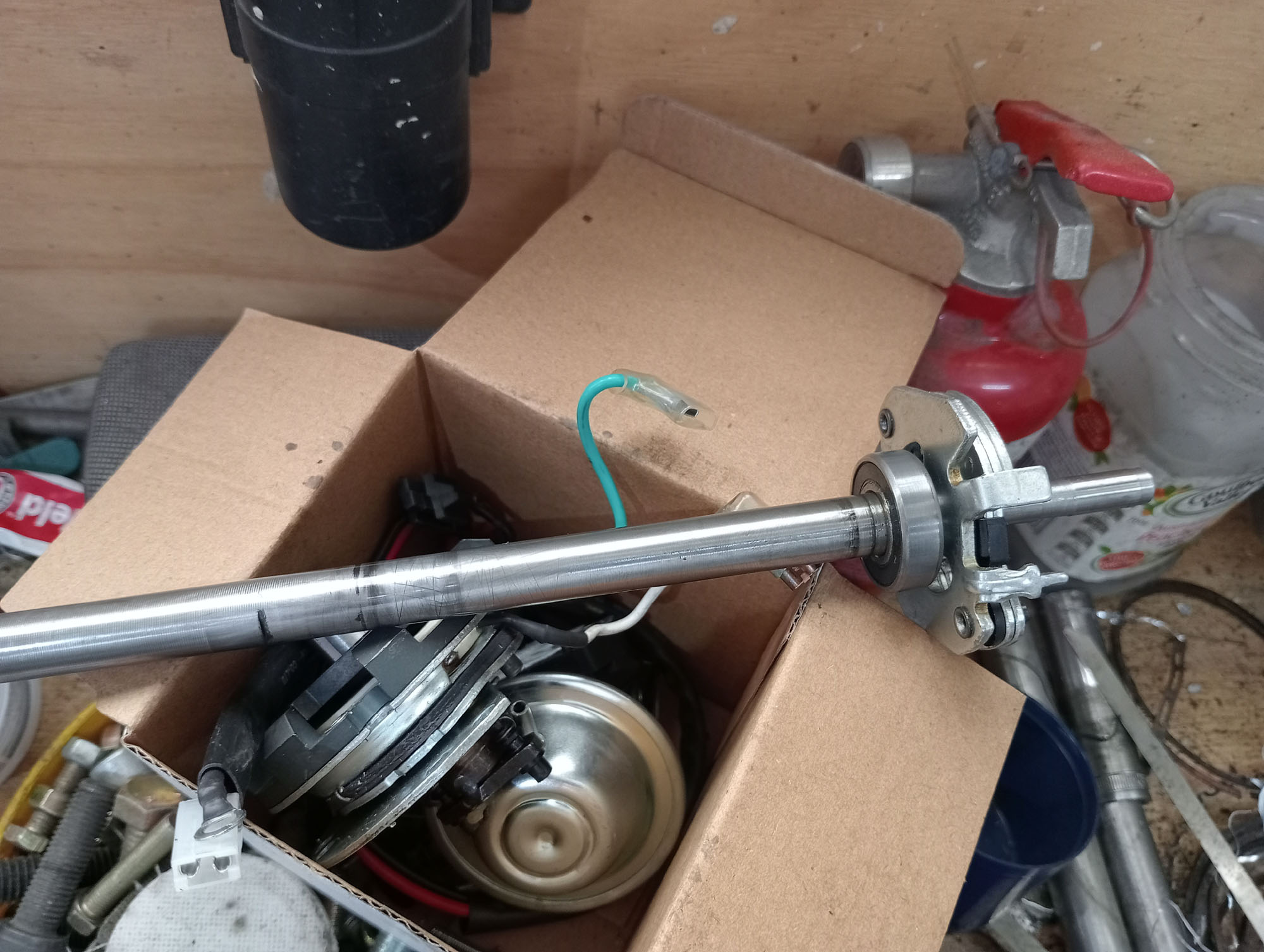
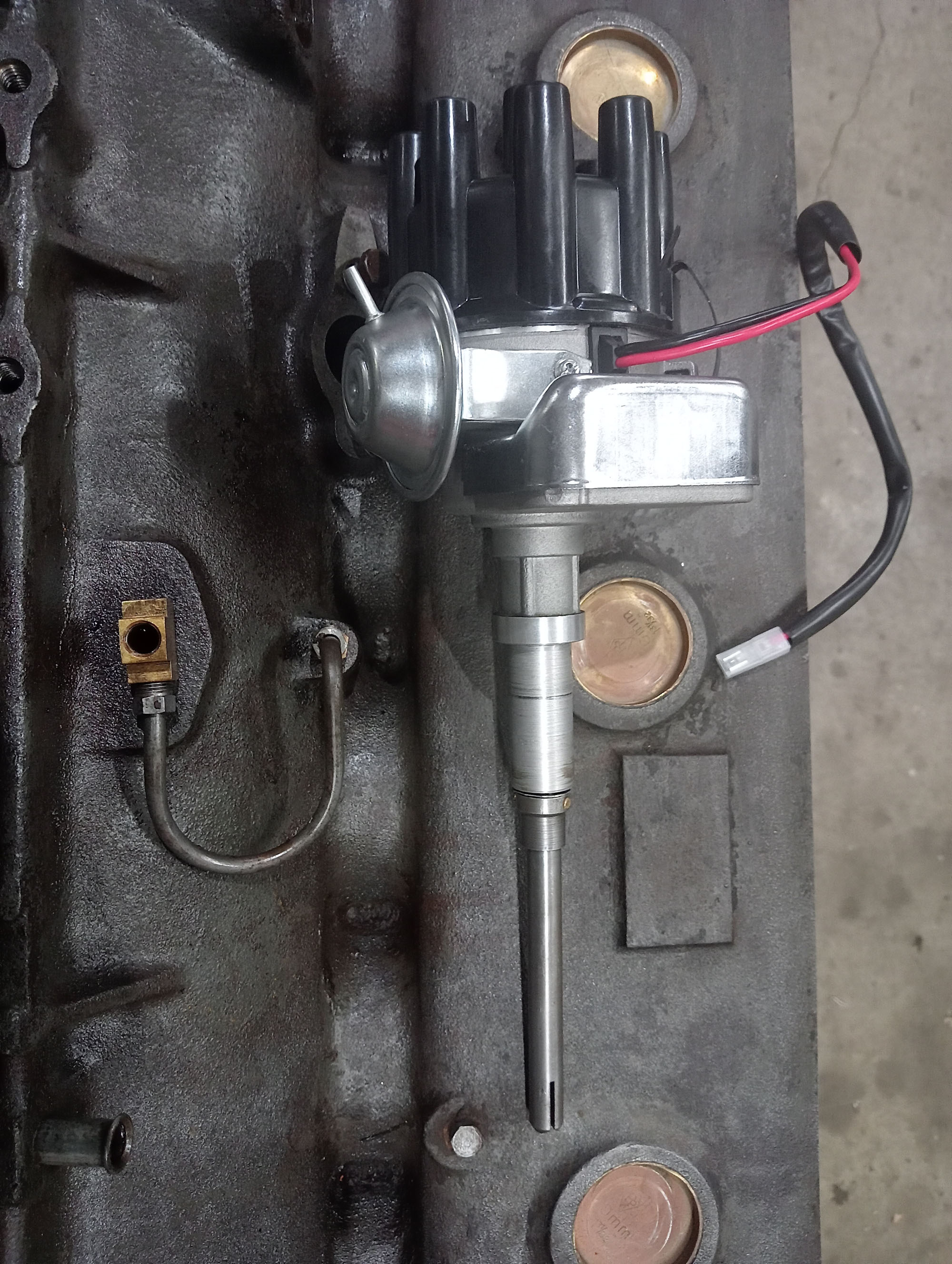
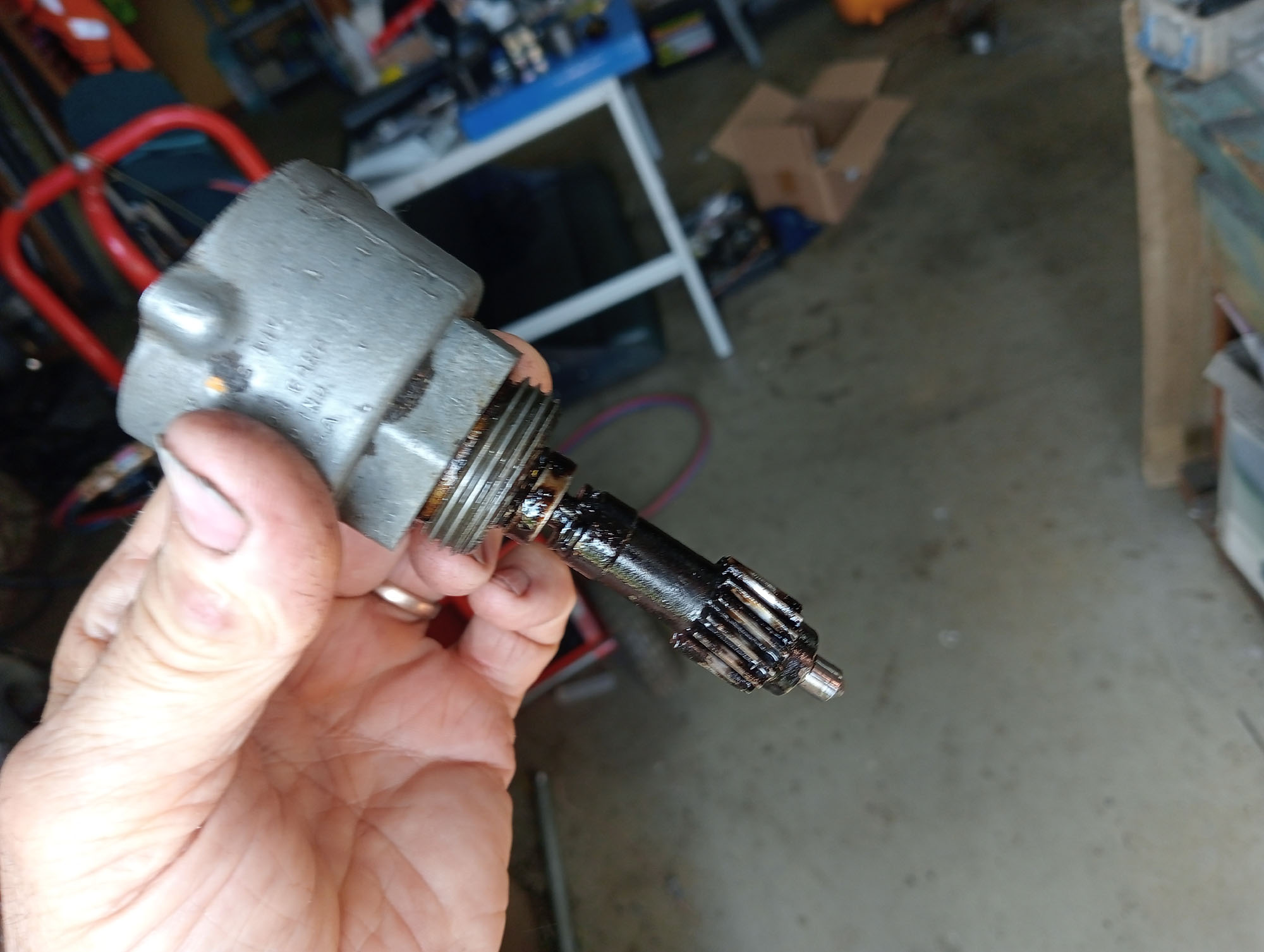
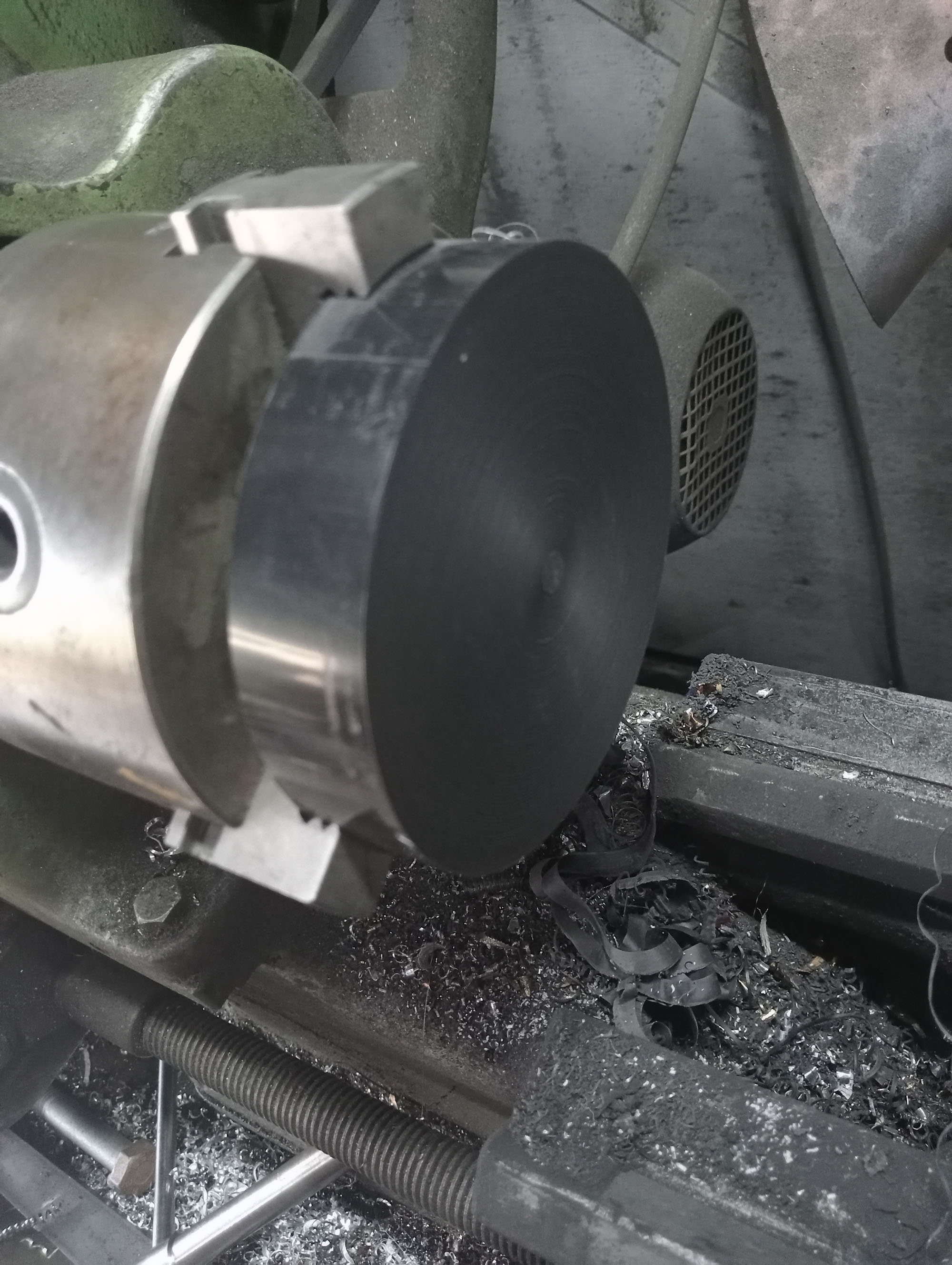
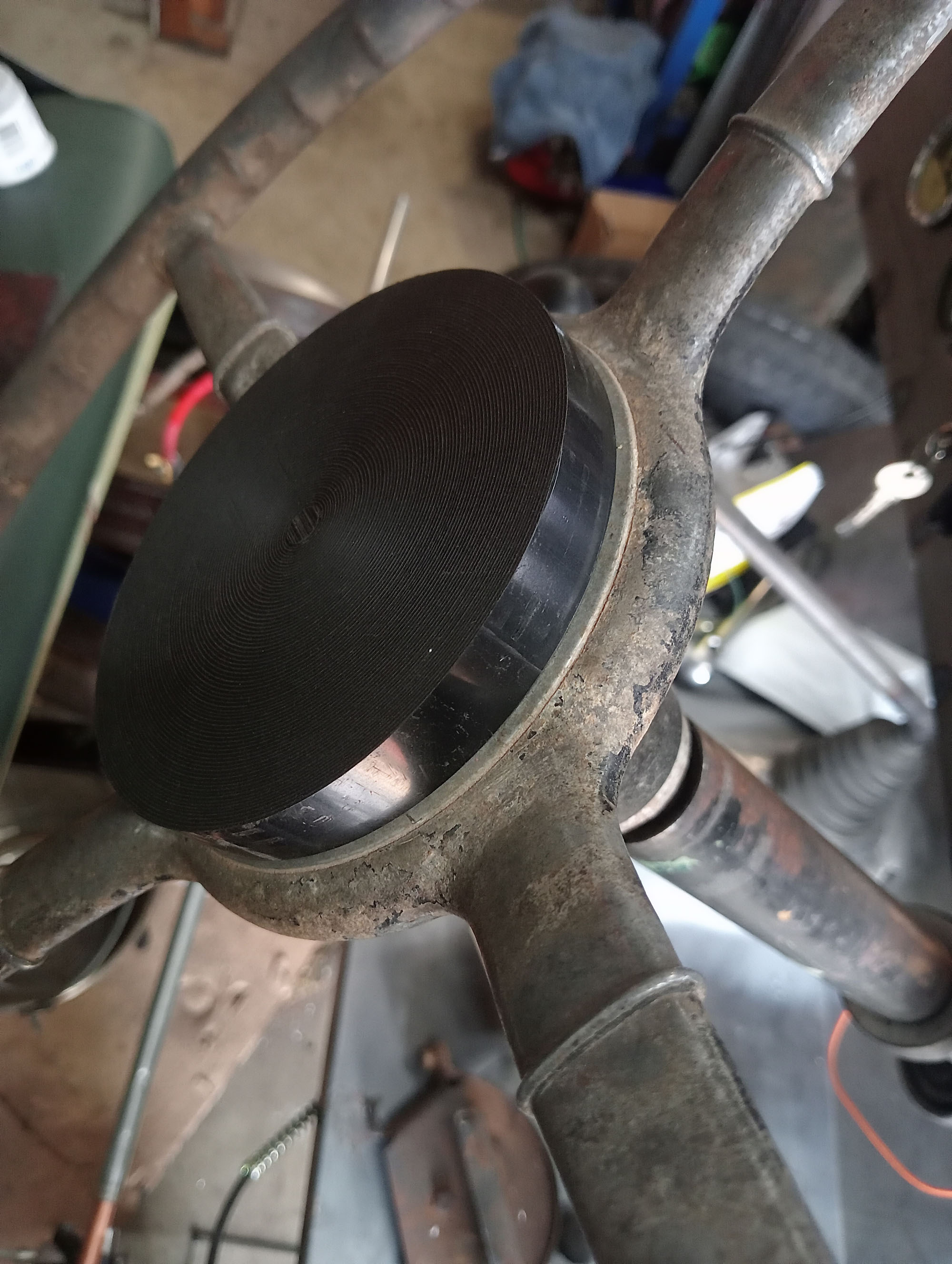
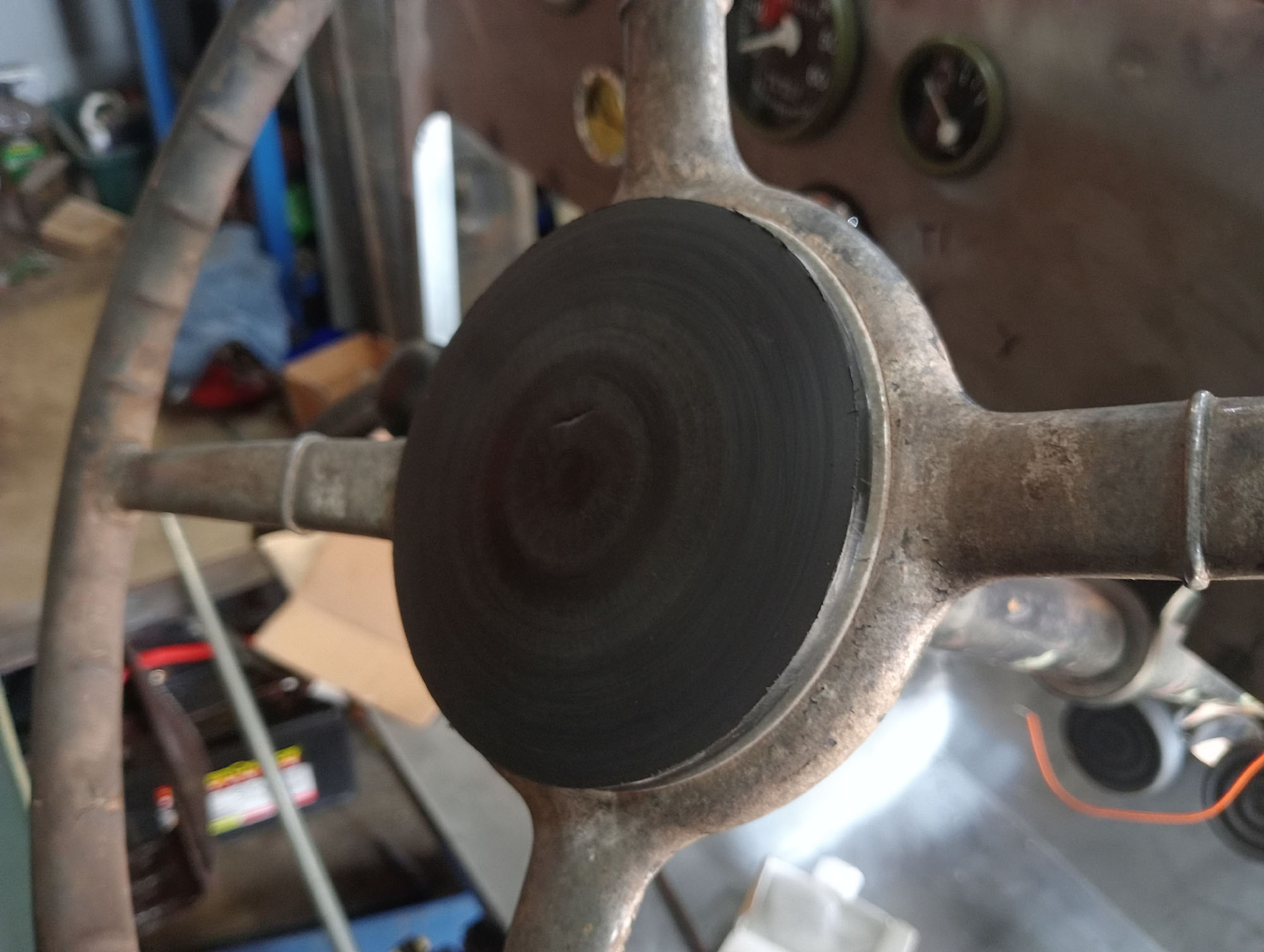
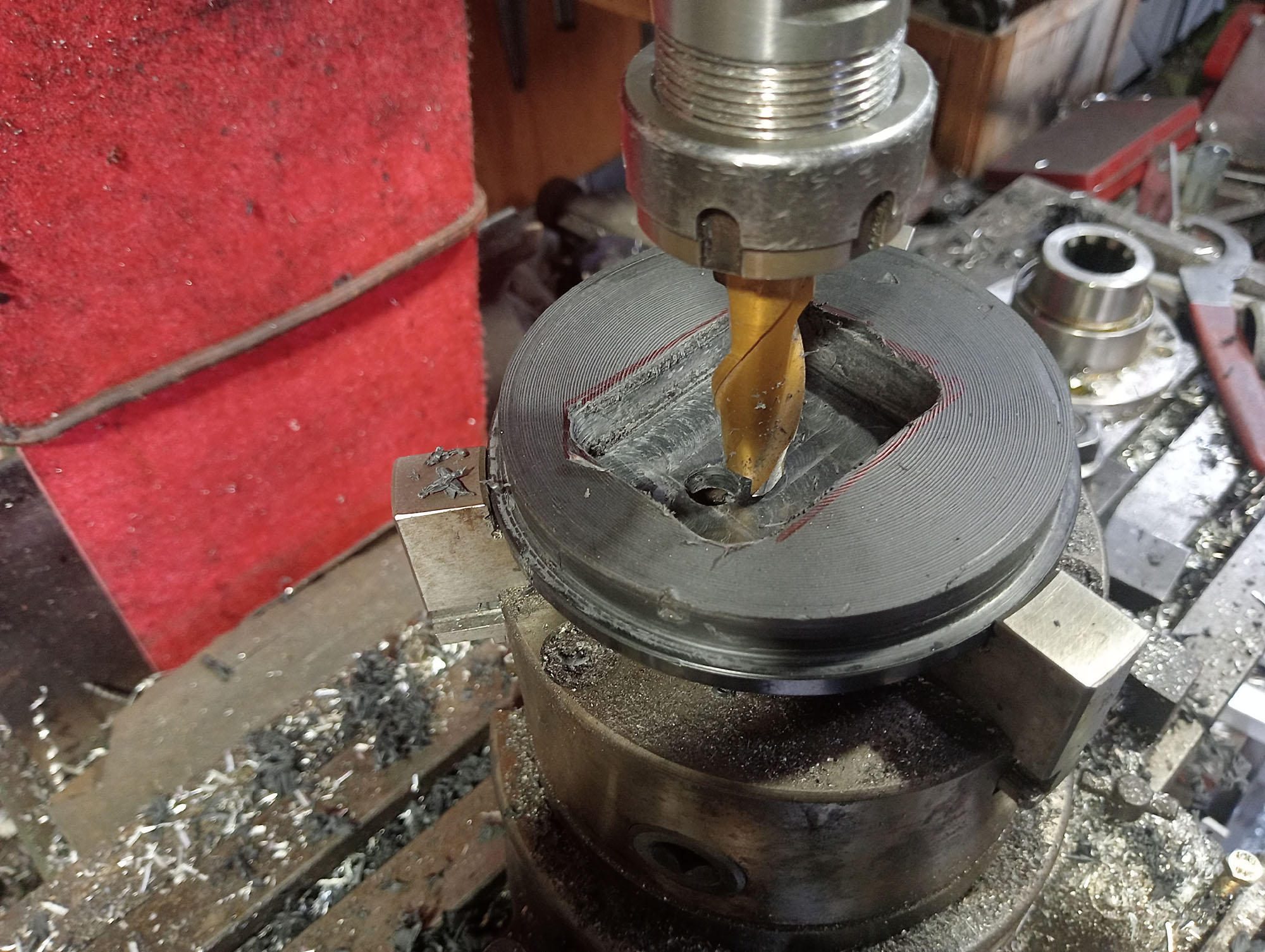
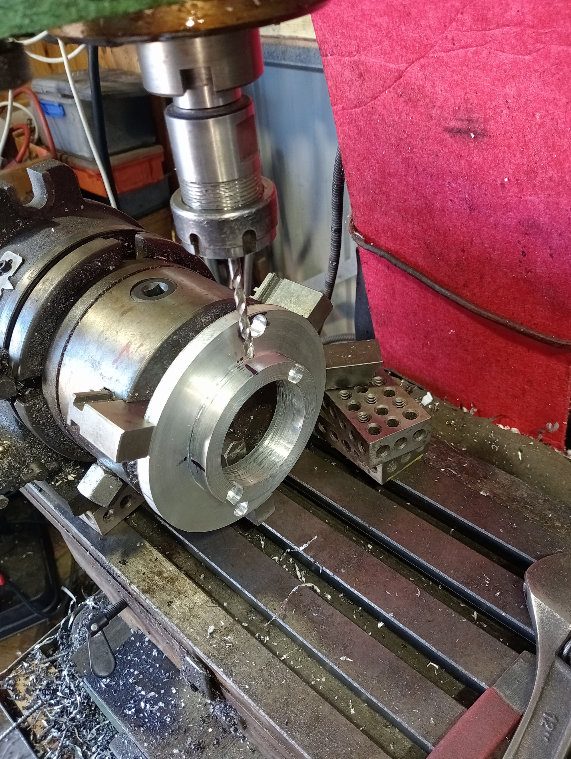
The clamp ring is in the wrong place so first Dismantle distributor . Hardest part of job was holding distributor body in lathe as too much force on the chuck tends to distort the diecast body. Turn down to diameter of hole in Packard block. I made a new clamp ring & glued to spigot (part 2 in photo) with JB Weld. Cut shaft to length ( gear dive is not needed) & modify shaft to accept lower shaft from a Packard distributor. (part 1) using the Packard attaching collar which incorporates a small universal joint to eliminate misalingment issues.

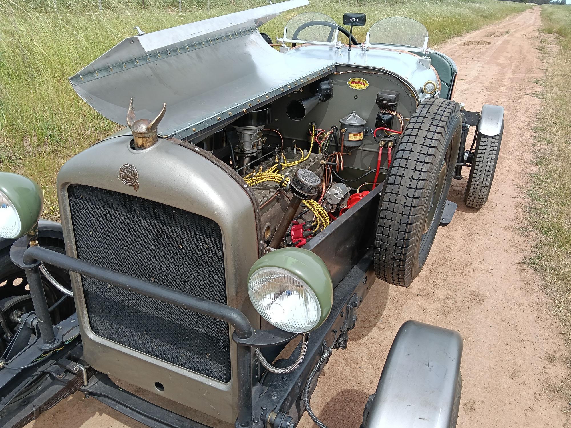
Manifolds
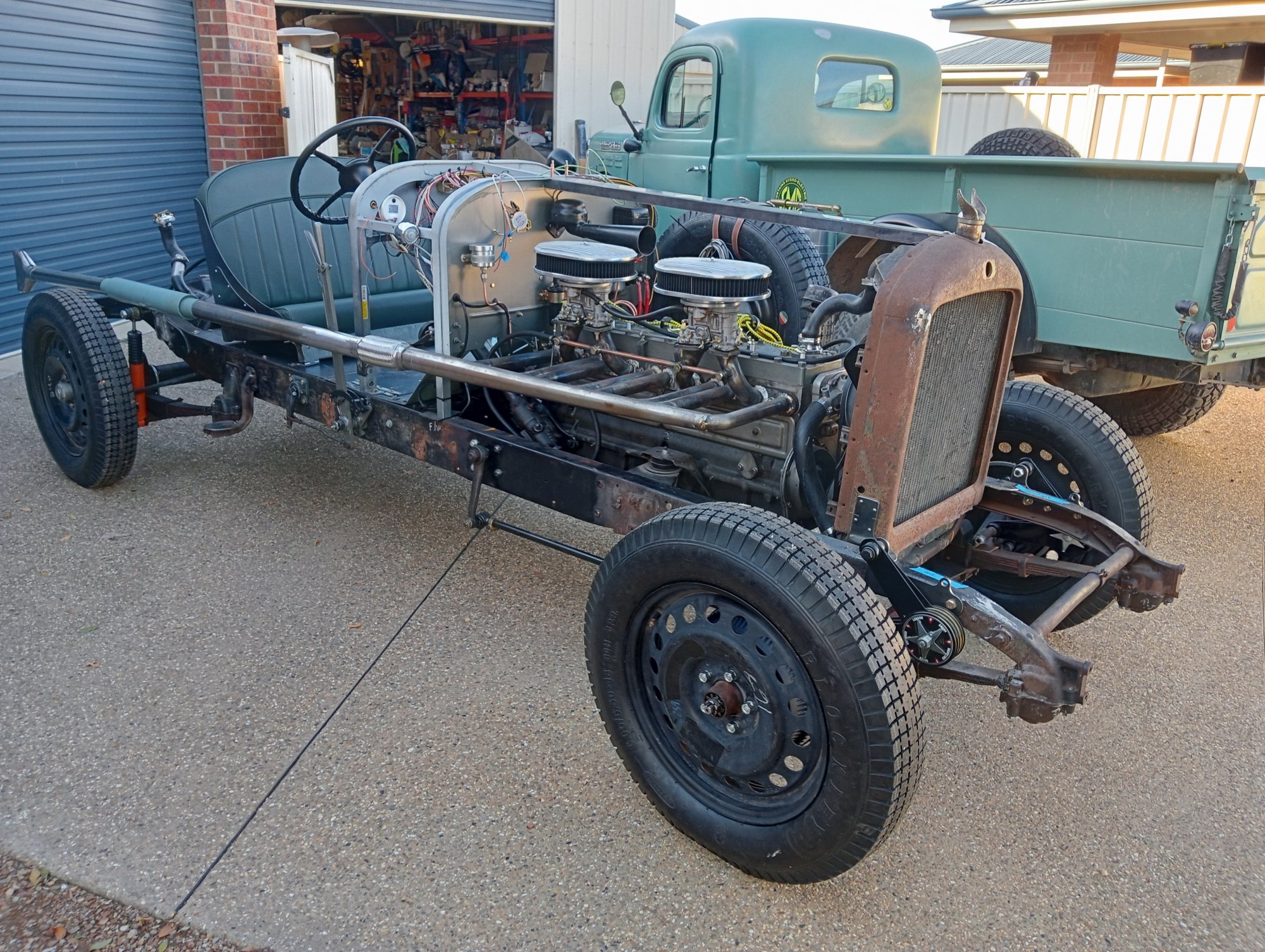
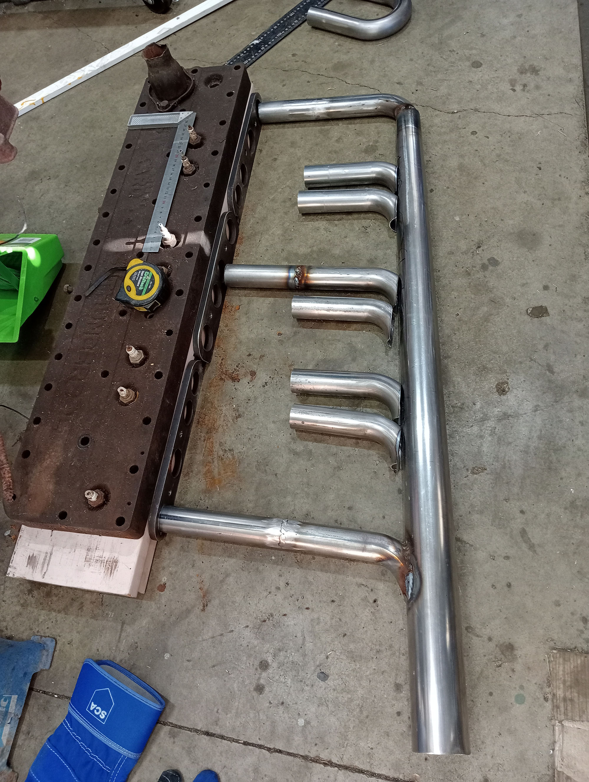
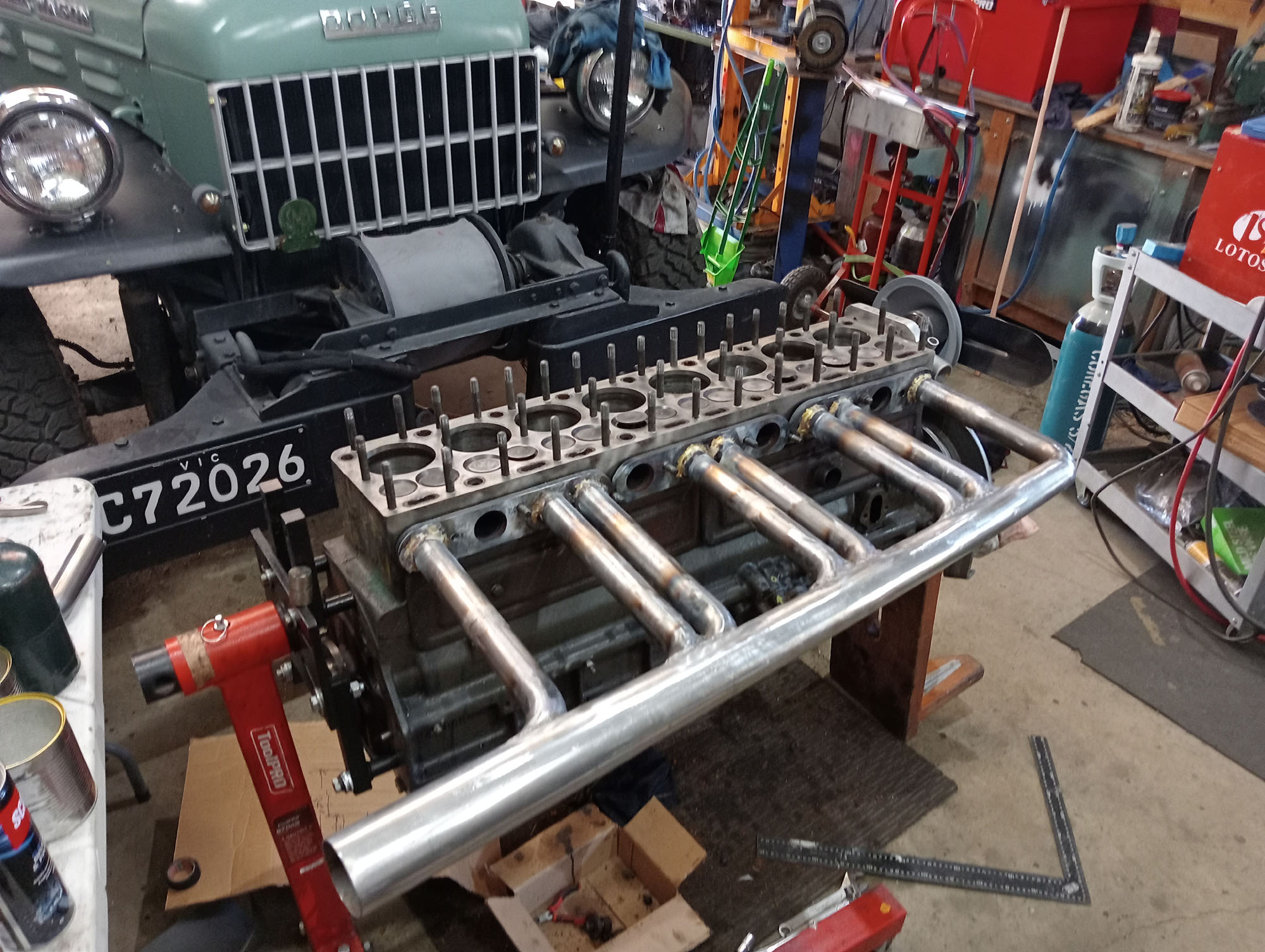
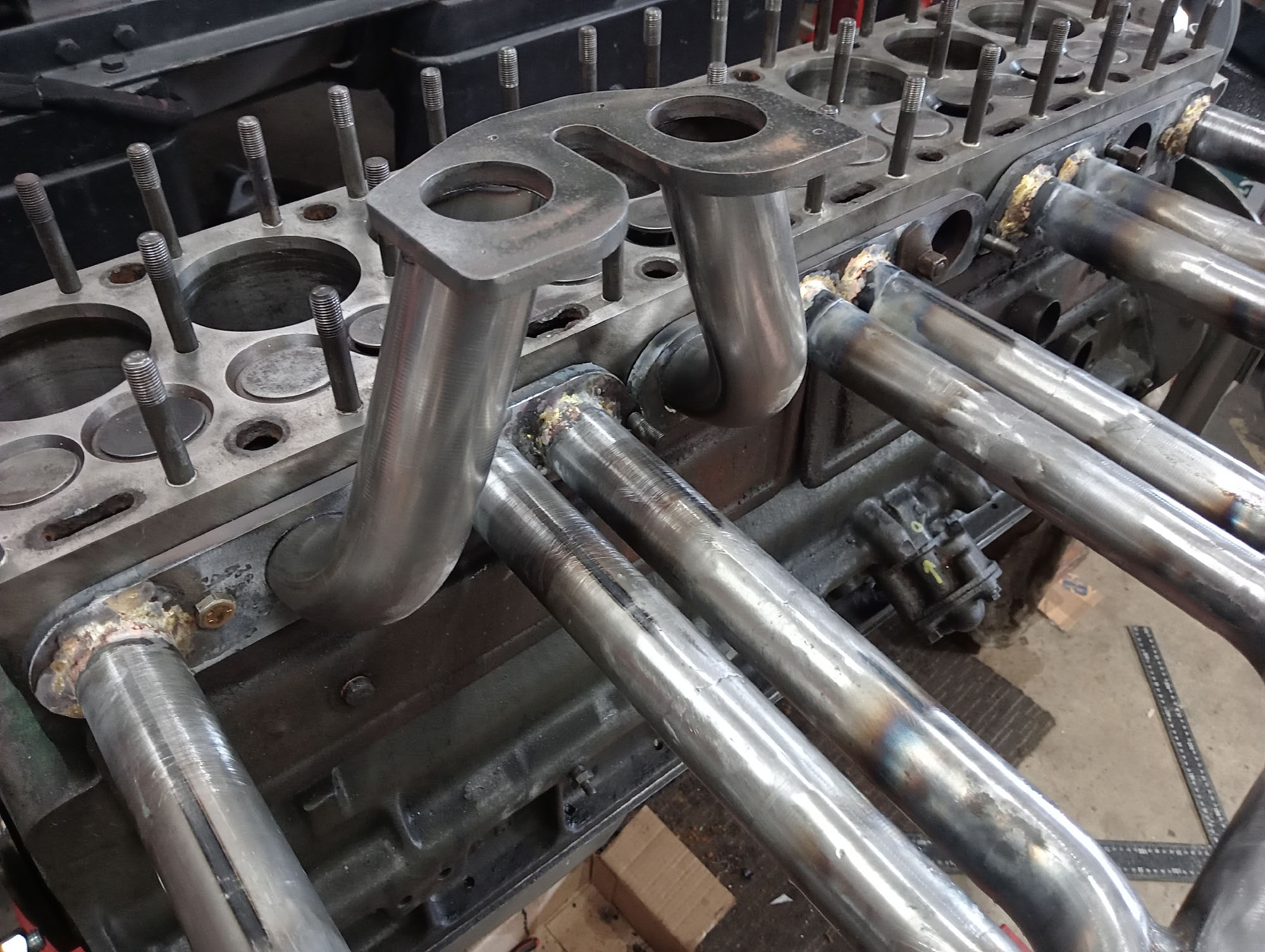
Amongst the parts that came with the engines were a number of exhaust manifolds and 2 barrel inlet manifolds. The style of car that I'm building lends itself to a set of Laker style pipes with an exhaust that runs along the side of the car rather than a concealed exhaust under the car as would be dictated by the original Packard manifolds.
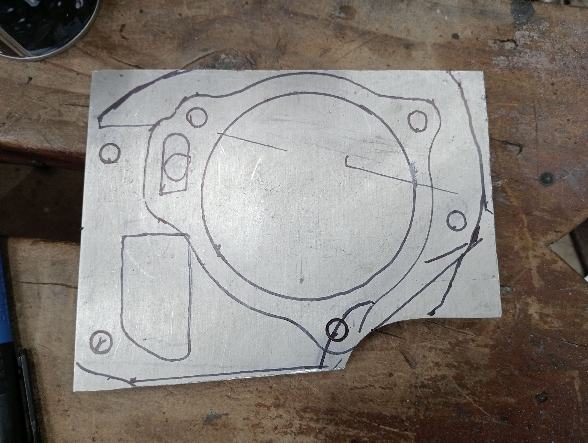
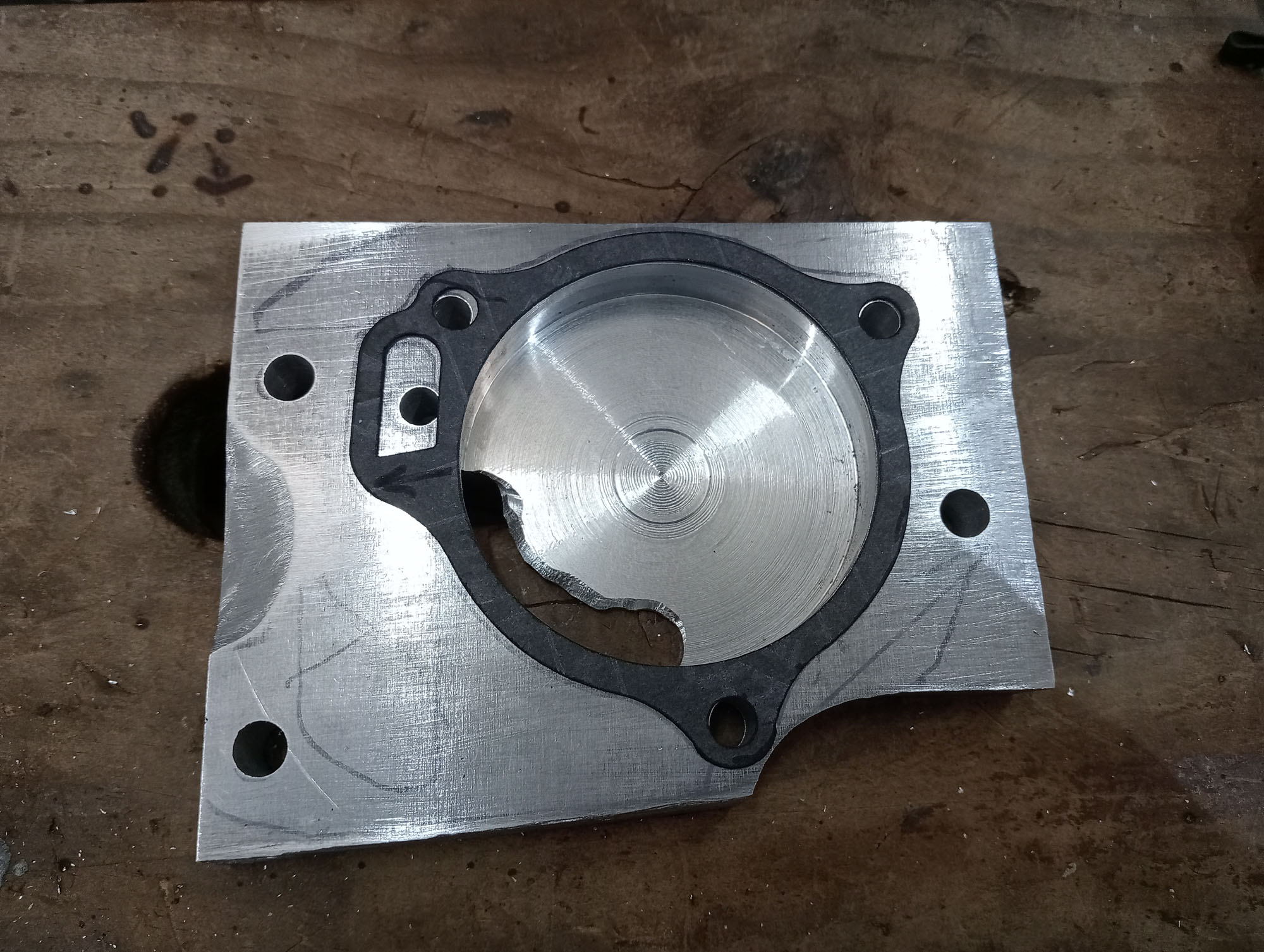
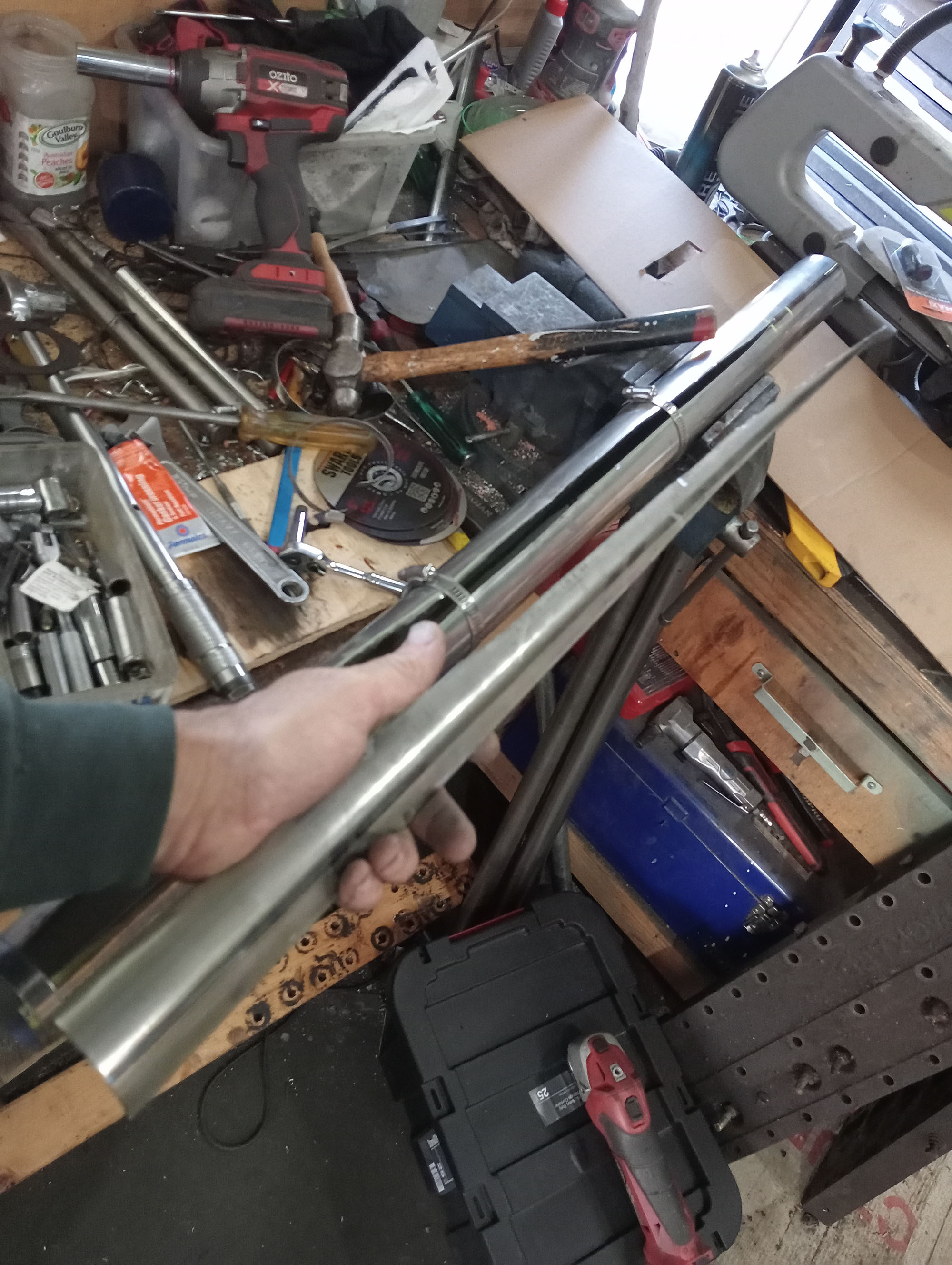
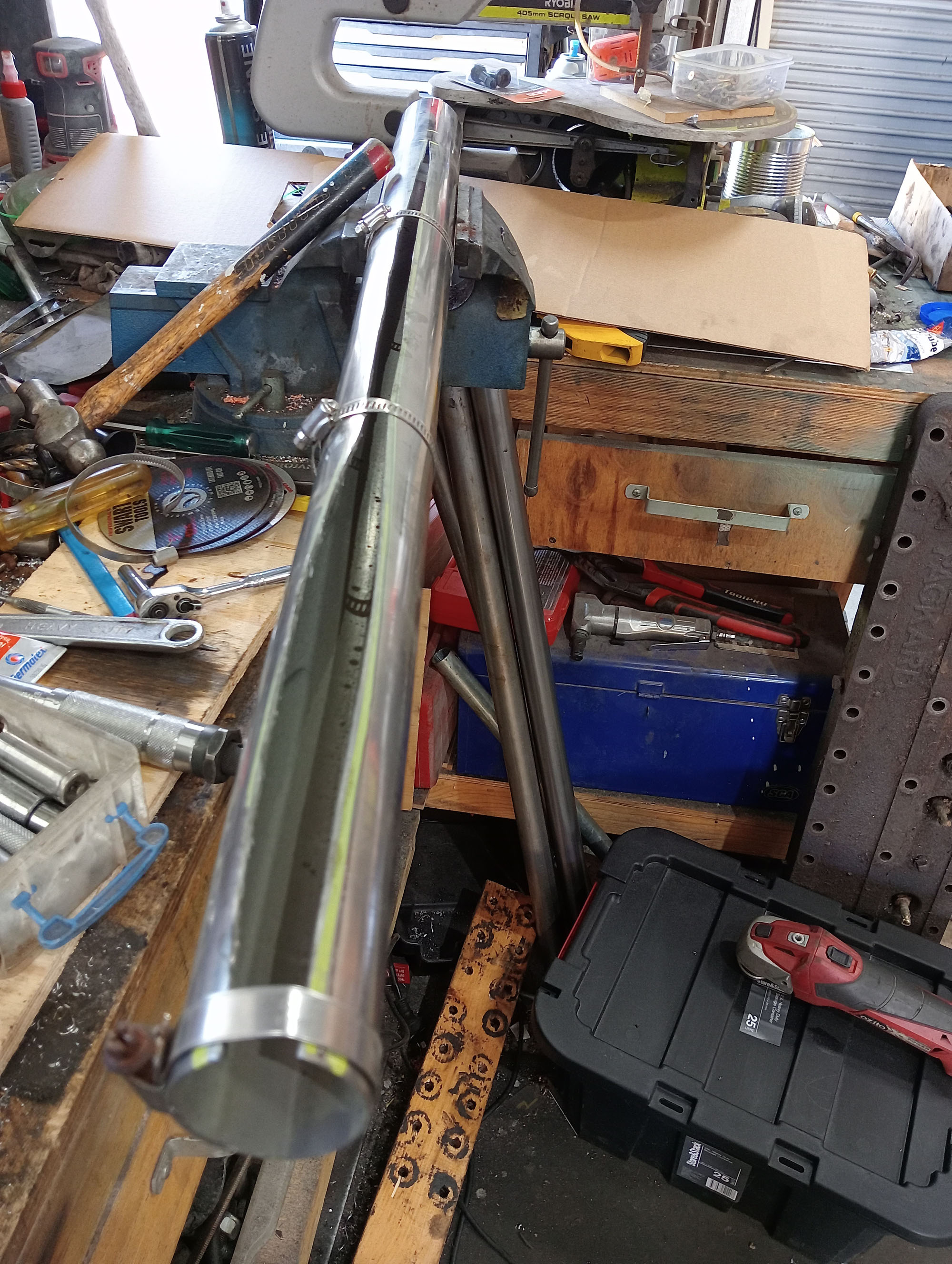
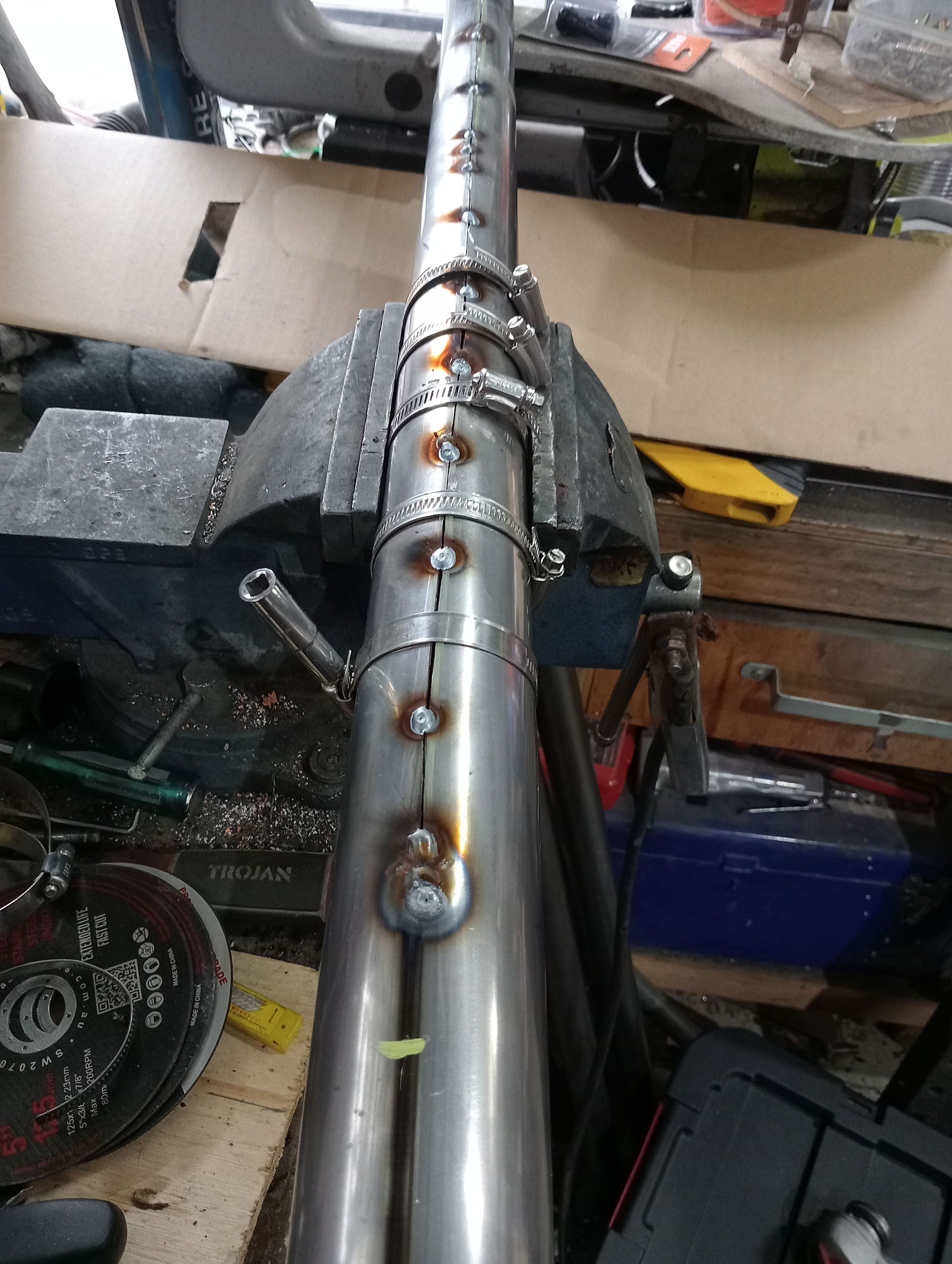
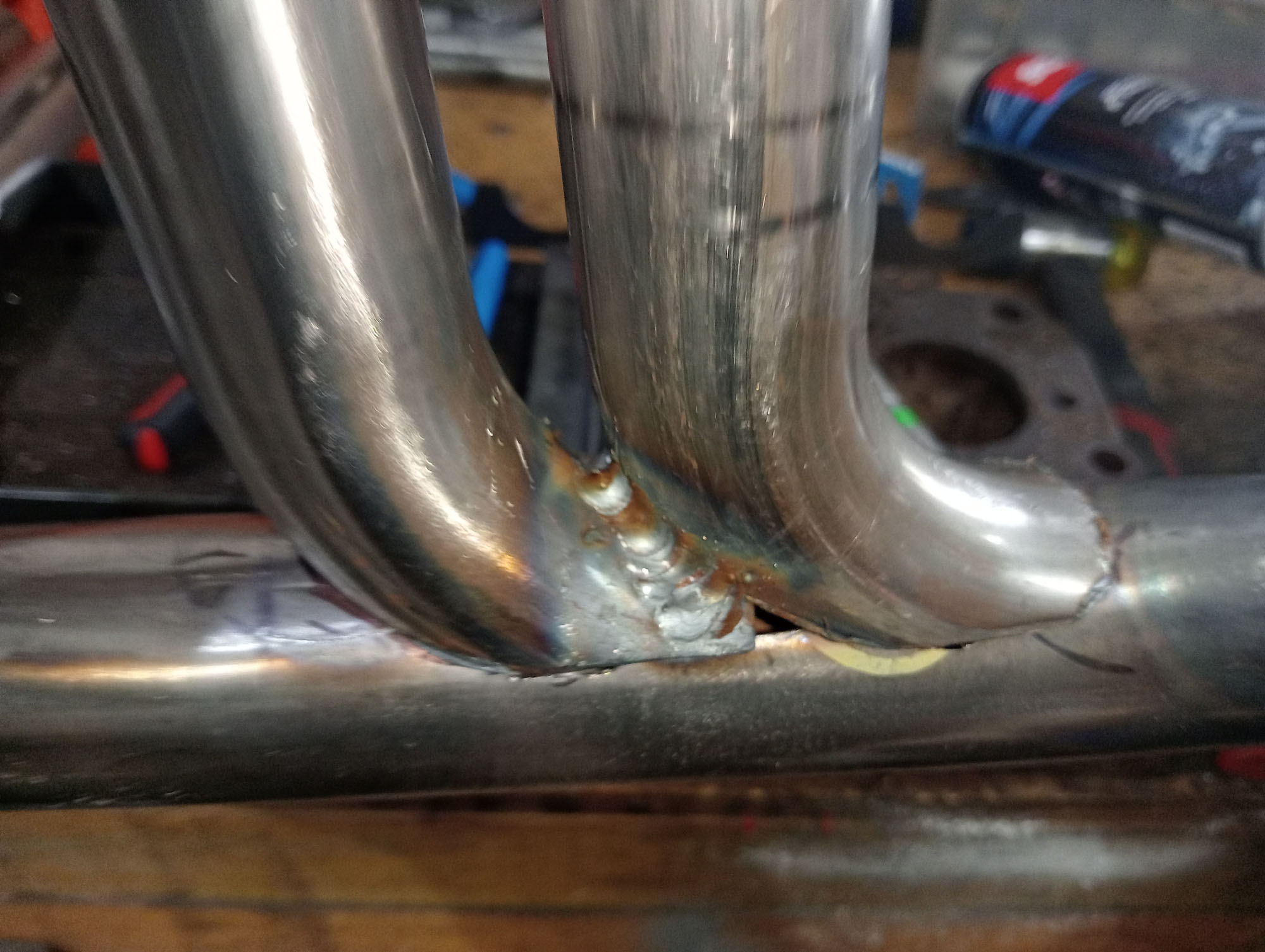
I made the plates that bolt to the block by copying an old manifold gasket into CAD and then plasma cut from 10mm steel plate. I used 1-1/2" exhaust pipe for the runners and make the tapered collector pipe by cutting a wedge from from a length of 2-1/2" exhaust pipe then closed it up with hose clamps & welded back together.
Inlet manifolds made the same way & mount a pair of Weber IDF40 carbs. The inlet ports are siamesed so each cylinder breathes through a 40mm venturi - effectively the same as having one 40mm carb per cylinder with equal length runners.
.
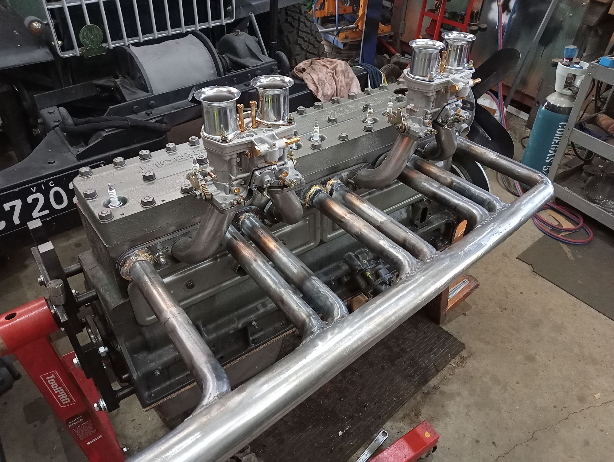
note these carbs have no choke hence the hand over the top
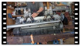
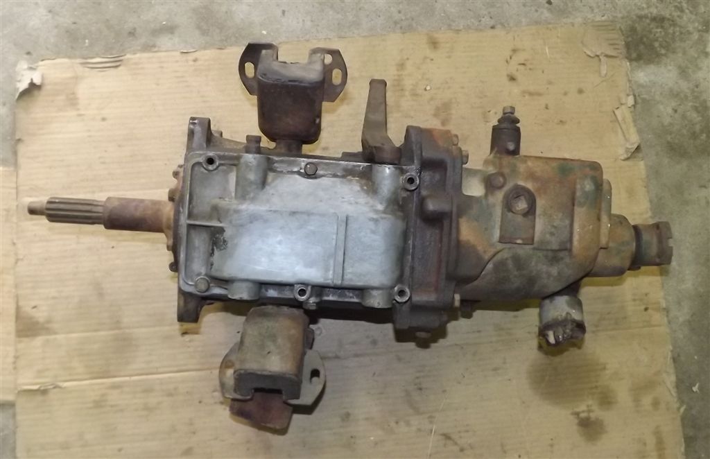
Clutch & Transmission
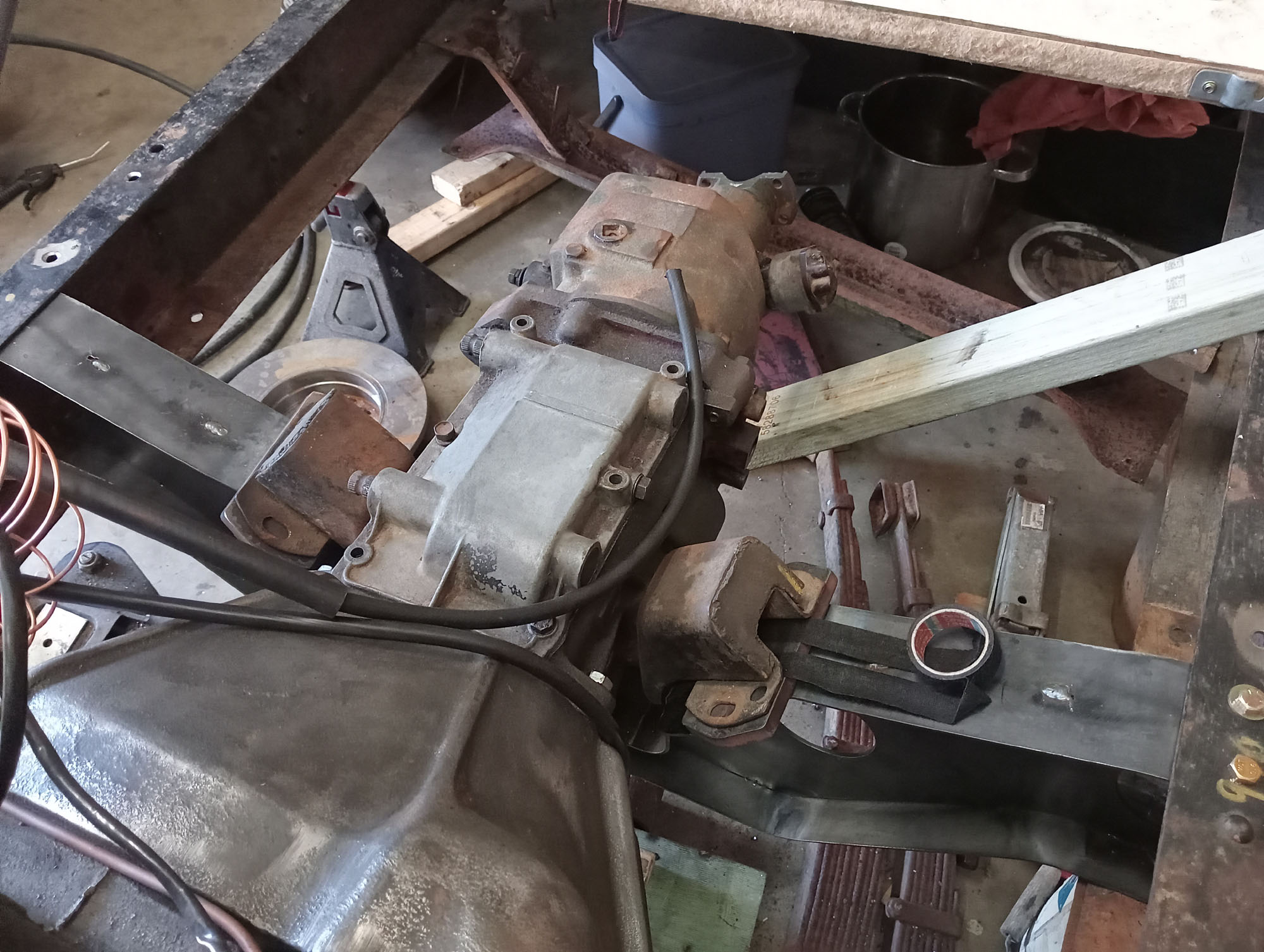
One of the engines had a Packard Ultramatic transmission, That's a very heavy (engine and transmission together is over 500kg) ) early 2 speed Manual shift 'Automatic' with a locking torque converter. A Speedster really needs a manual transmission and I was lucky enough to have a query in a Facebook group answered by a bloke in Sunbury who had a Packard 3 Speed with R9 Overdrive that was no longer required. $200 well spent. Luckily one of my Packard engines had a Manual bell-housing and flywheel so the Packard 3 speed would be an easy bolt up.
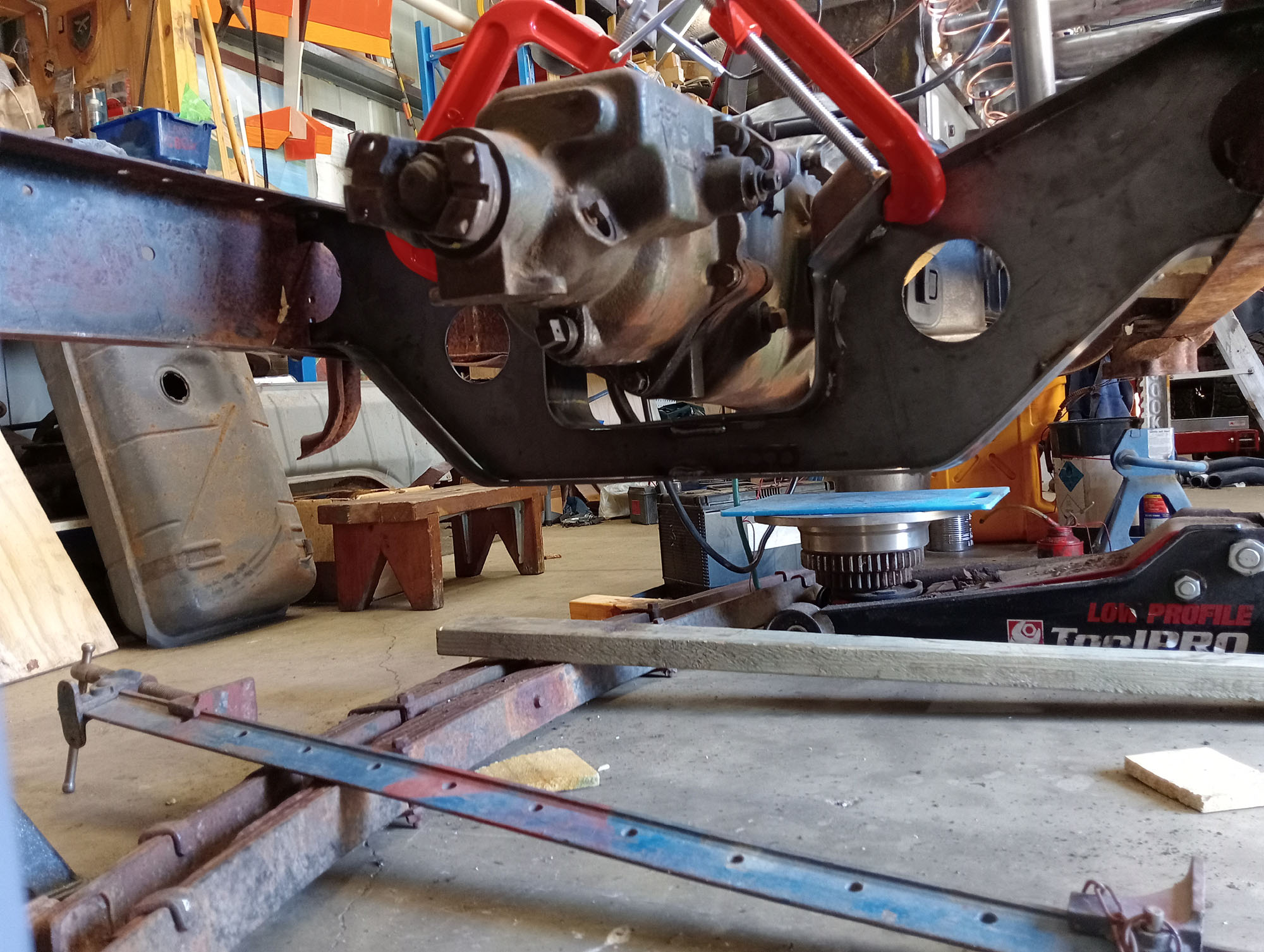
I needed to remove a crossmember & replace with one I fabricated which incorporated gearbox mounts, The original Chrysler gearbox was mounted to the chassis with brackets each side of the bellhousing. VSI-33 allows for new mounts and crossmembers to be used for mounting alternative engines of the era.
There was no clutch or pressure plate but I read online that a 10" V8 Ford Flathead pressure plate might fit so I found a seller on eBay who measured up the bolt holes on his pressure plate & it was a match. The Gearbox input spline is the same as a Holden V8 so I am using a Commodore clutch plate
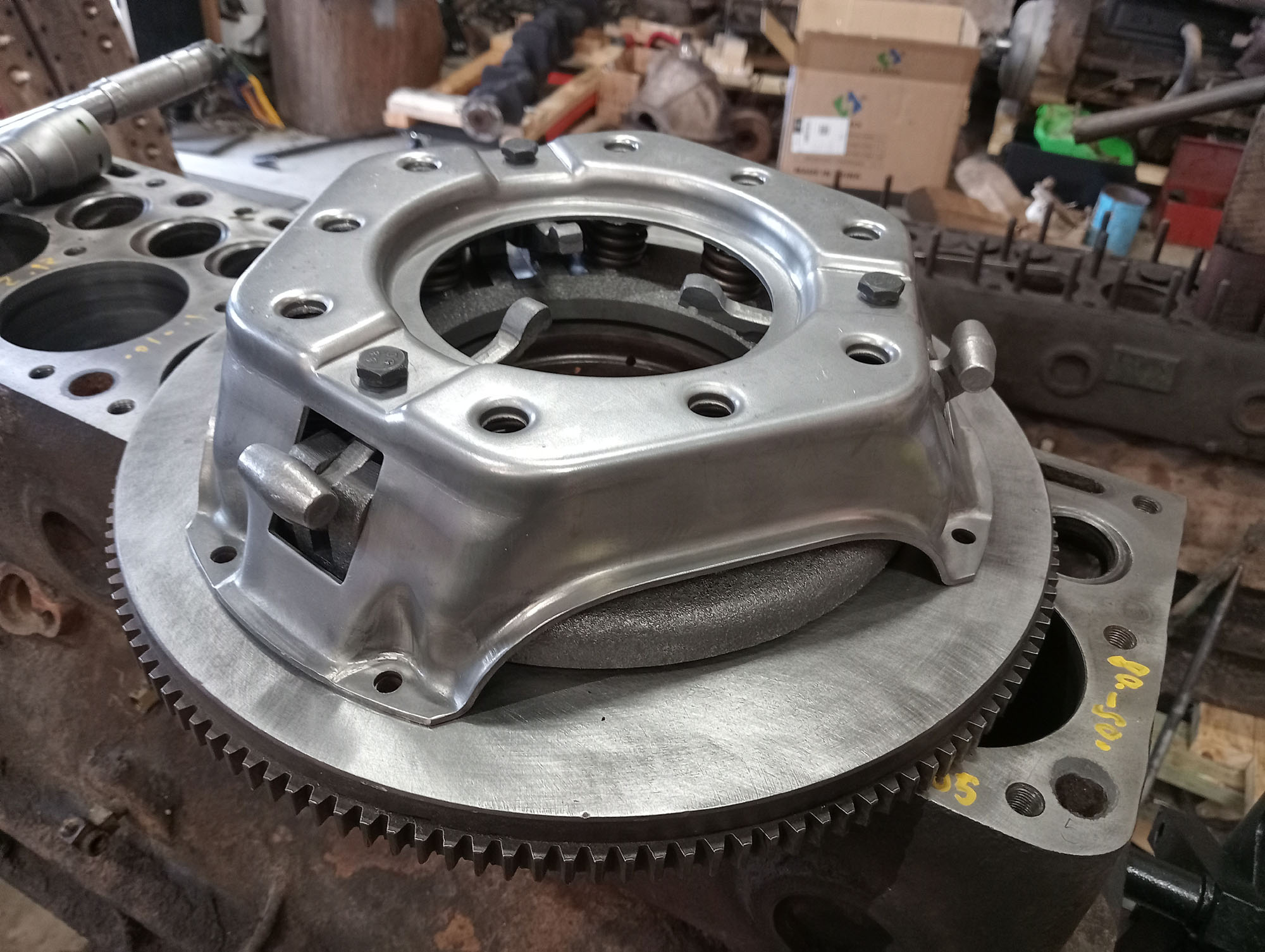
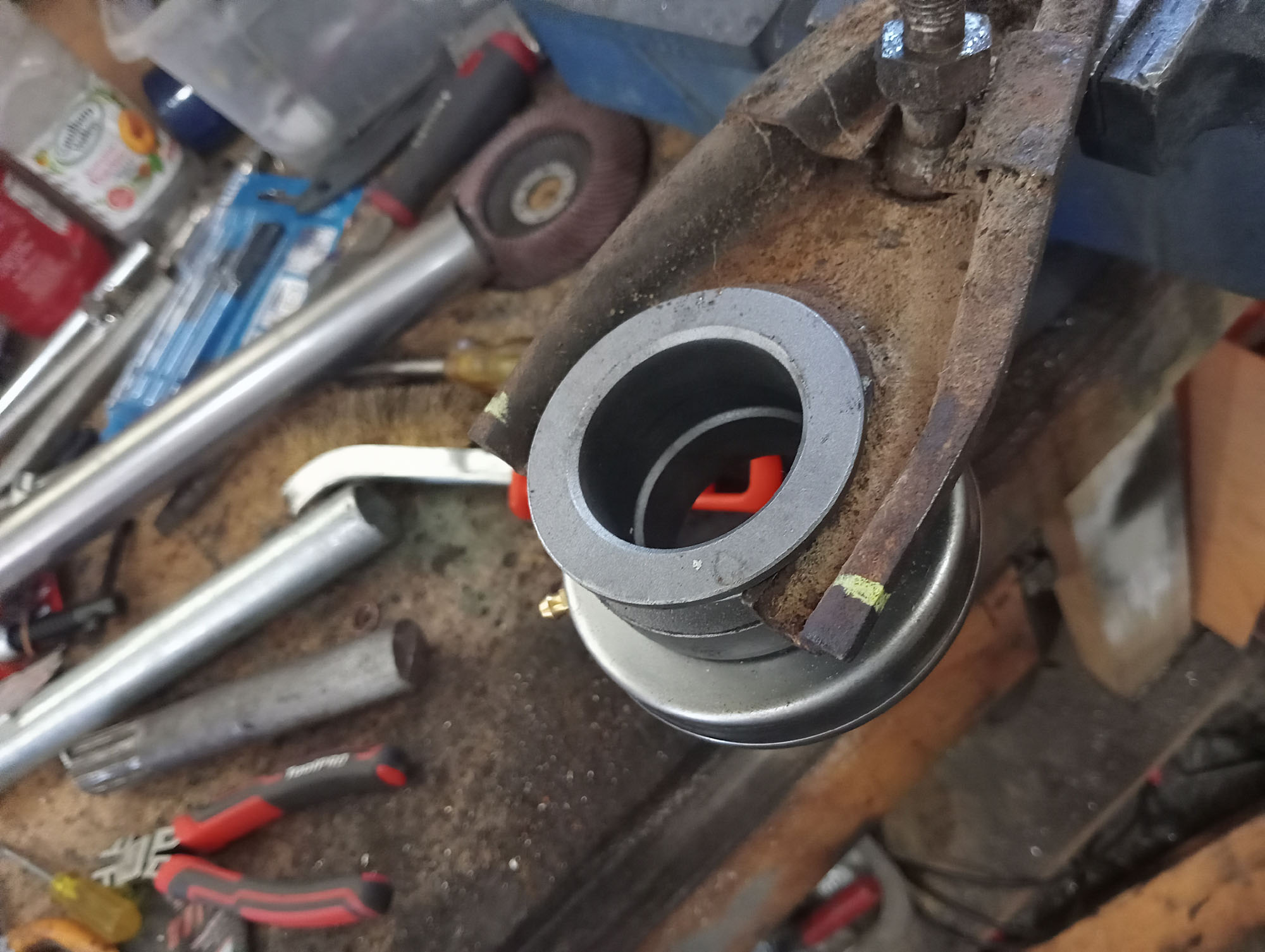
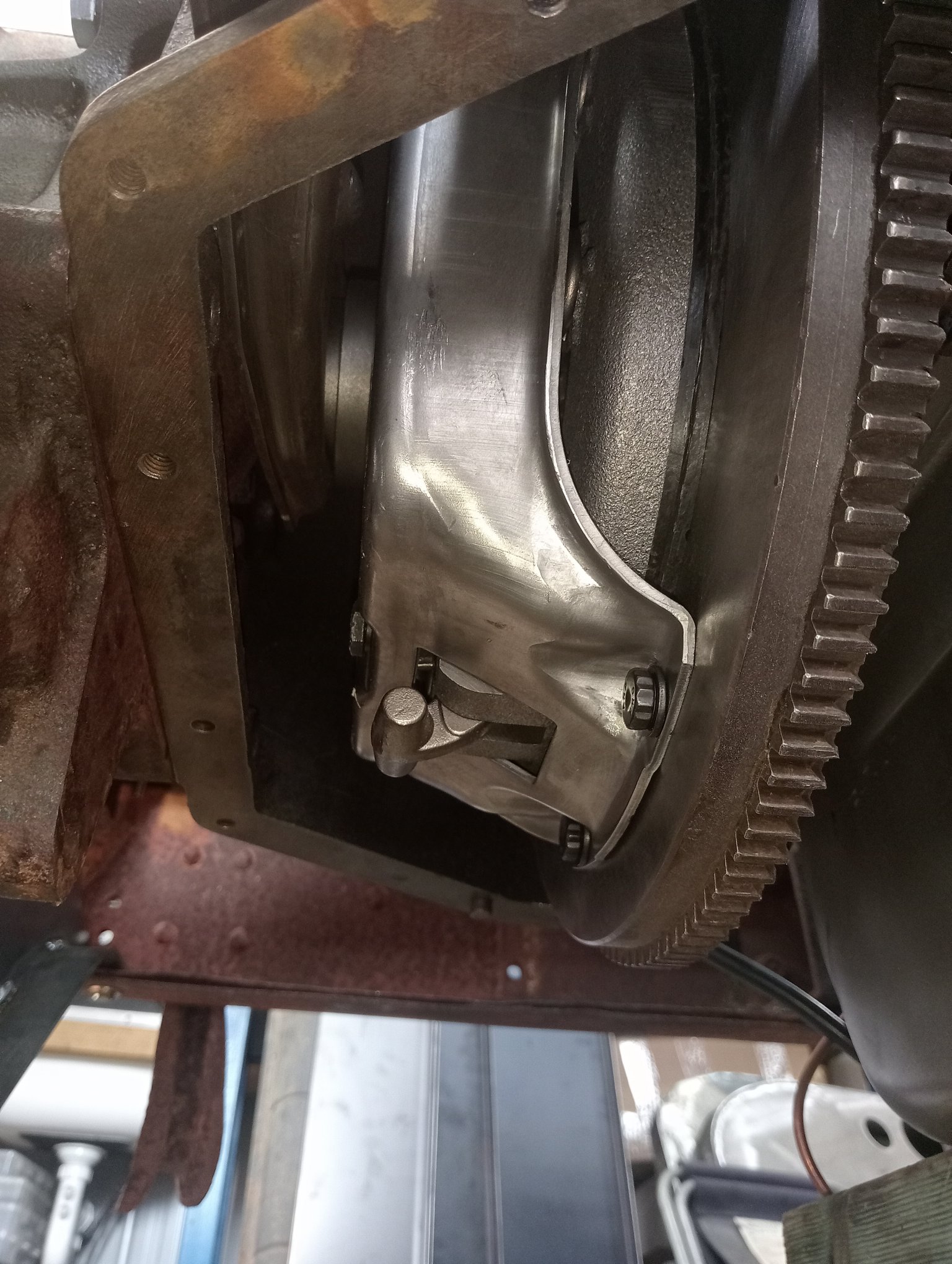
The throw out bearing is Ford V8 , and I made the bearing retainer to fit the input housing sleeve & the Packard clutch fork. And using what I have laying about as an unlikely accompaniment I have used a Series 2 Land Rover Clutch Master & slave cylinder.
R9 Overdrive
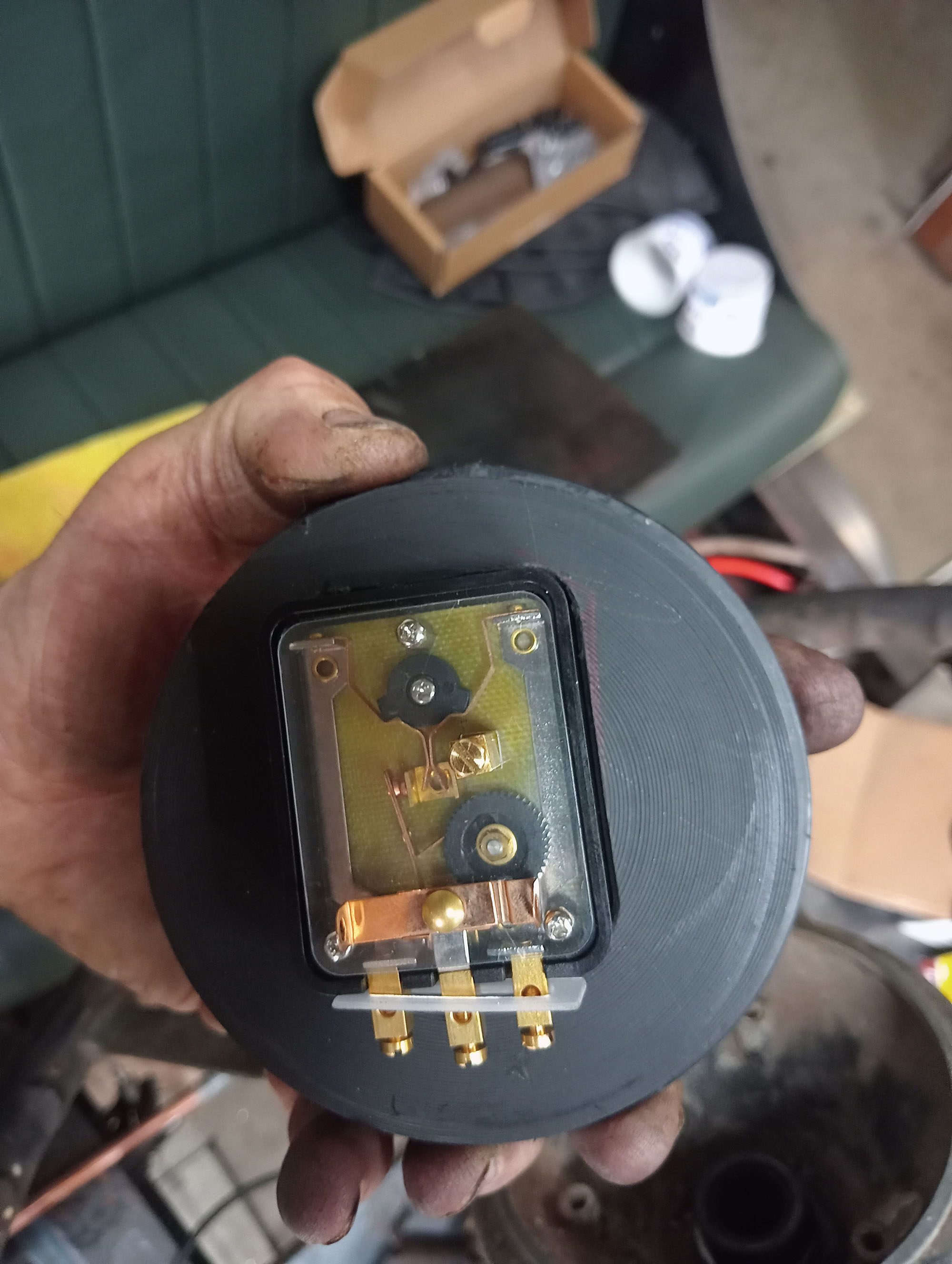
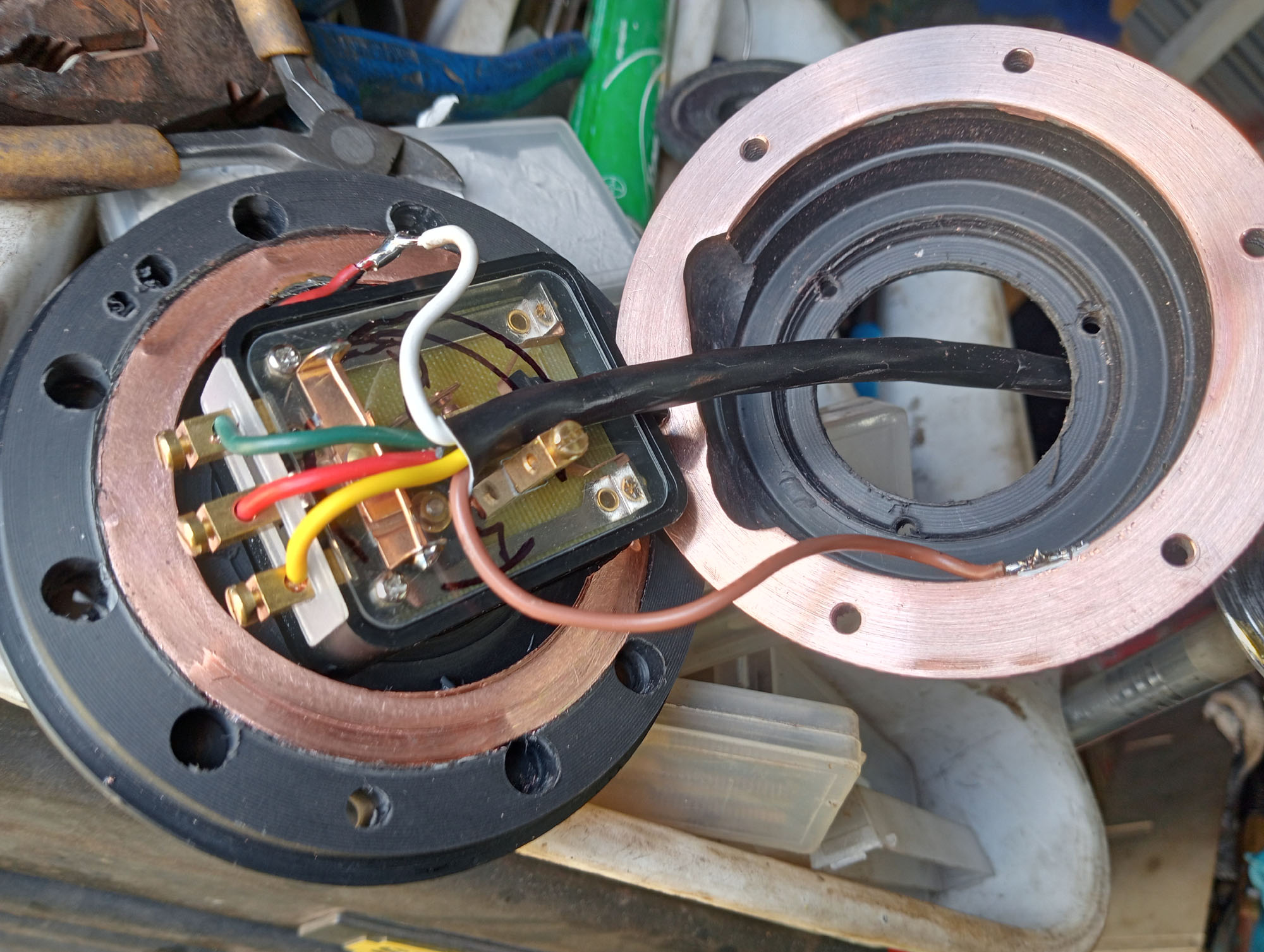
The overdrive on vintage cars isn't just a 5th gear mounted on the back of your 4 speed gearbox, in the Case of the Borg Warner R6 to R10 iterations that were used on a lot of American cars they are mounted behind the gearbox (in this case in place of the output housing) and consist of a planetary gear assembly that is engaged by a sliding collar, usually operated via a T-handle & cable and a solenoid that locks a pawl on the outer gear ring. In addition there is a governor that disables the overdrive at speeds below about 30 mph by releasing the solenoid. Due to its design the Overdrive can't work in reverse, the reverse selecor rod in the transmission acts on a lockout pin to prevent it.
At 60 mph the engine will be doing 3000RPM in top gear , Engaging Overdrive will drop the engine speed back to 2000RPM.
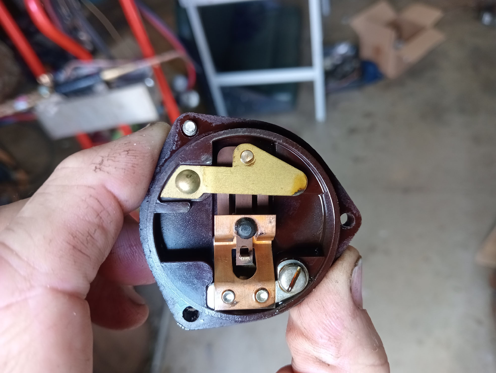
The Solenoid I bought from eBay USA came with the warning "untested" and a lable that said 'check inside" . Translation for "untested" actually means "we tested & it don't work" I know this because you would not sell a Solenoid for the price I paid when a very simple test can determine if it works.
When I opened the case the Solenoid was a rusticle, Plunger stuck solid - I did not give much hope, Dismantled & threw the parts in Evaporust , One of the contacts had a broken point, I could make a new contact spring from 0.6mm spring sheet but realised I could modify the wiring and get the same function from an external relay.
After cleaning, reassembly & some minuscule use of rust preventative / lubrication the solenoid now works like a champion.
Last part of the puzzle was the missing solenoid spacer / oil seal housing, I figured I'd make one and asked if anyone had one they could measure on Packardinfo.com , lo & behold one very helpful member had some in a drawer and kindly posted it to me. .
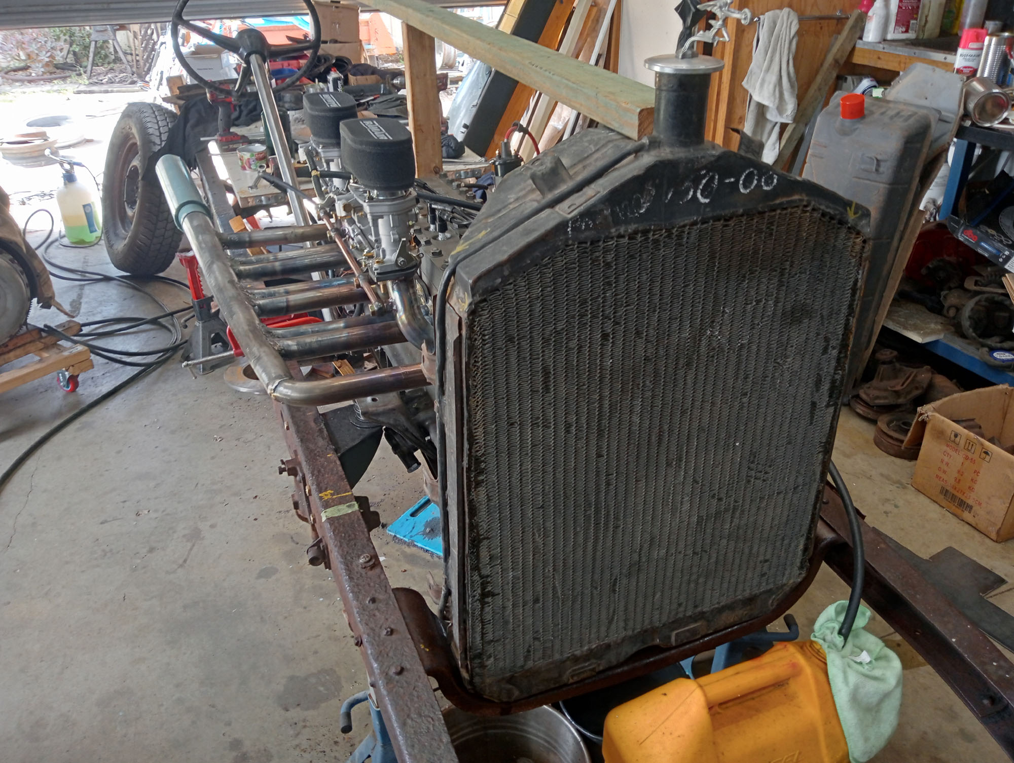
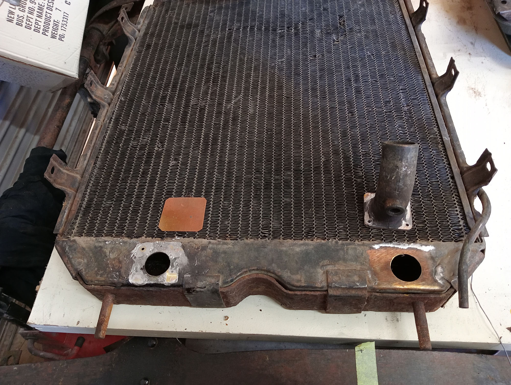
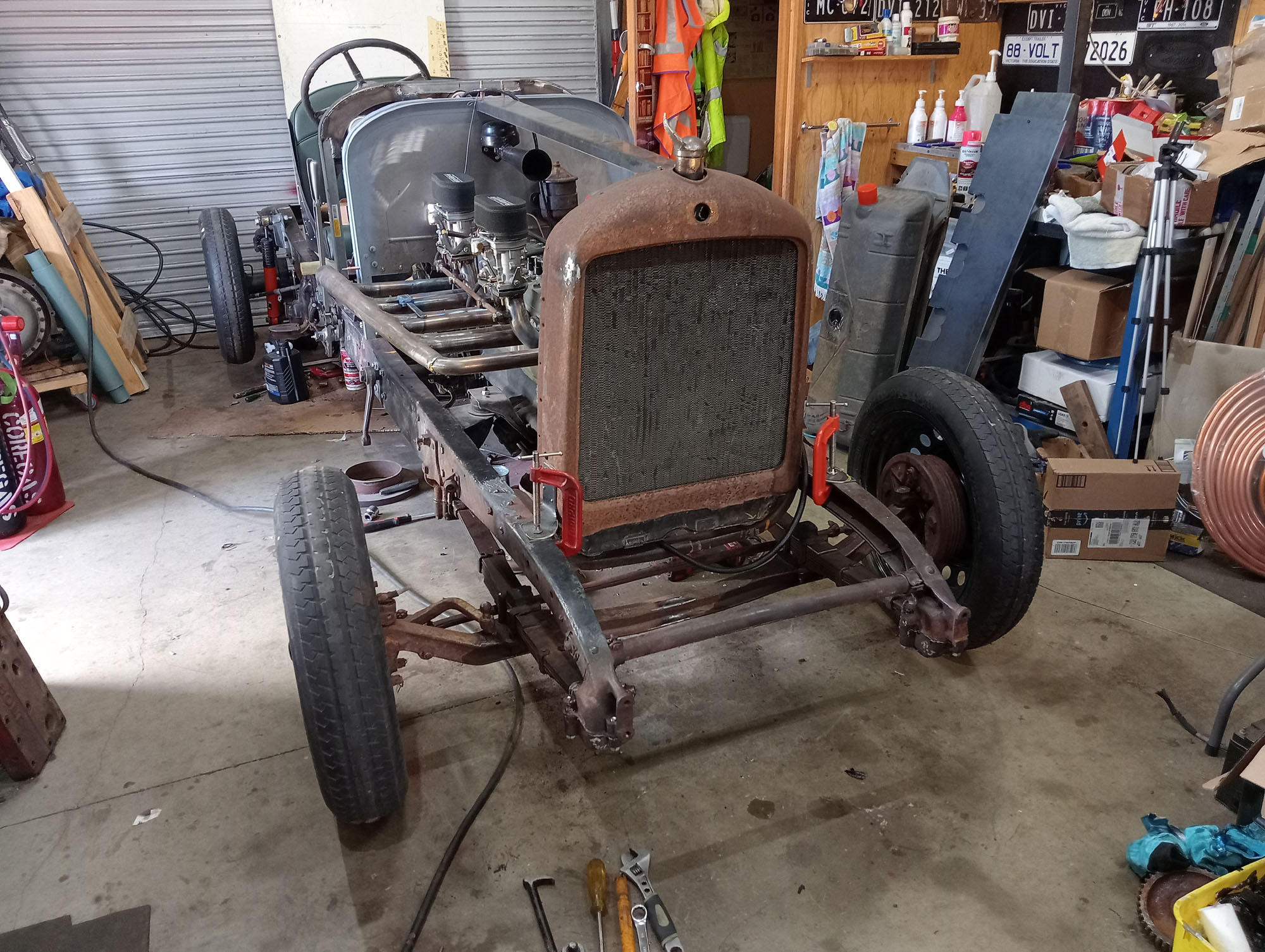
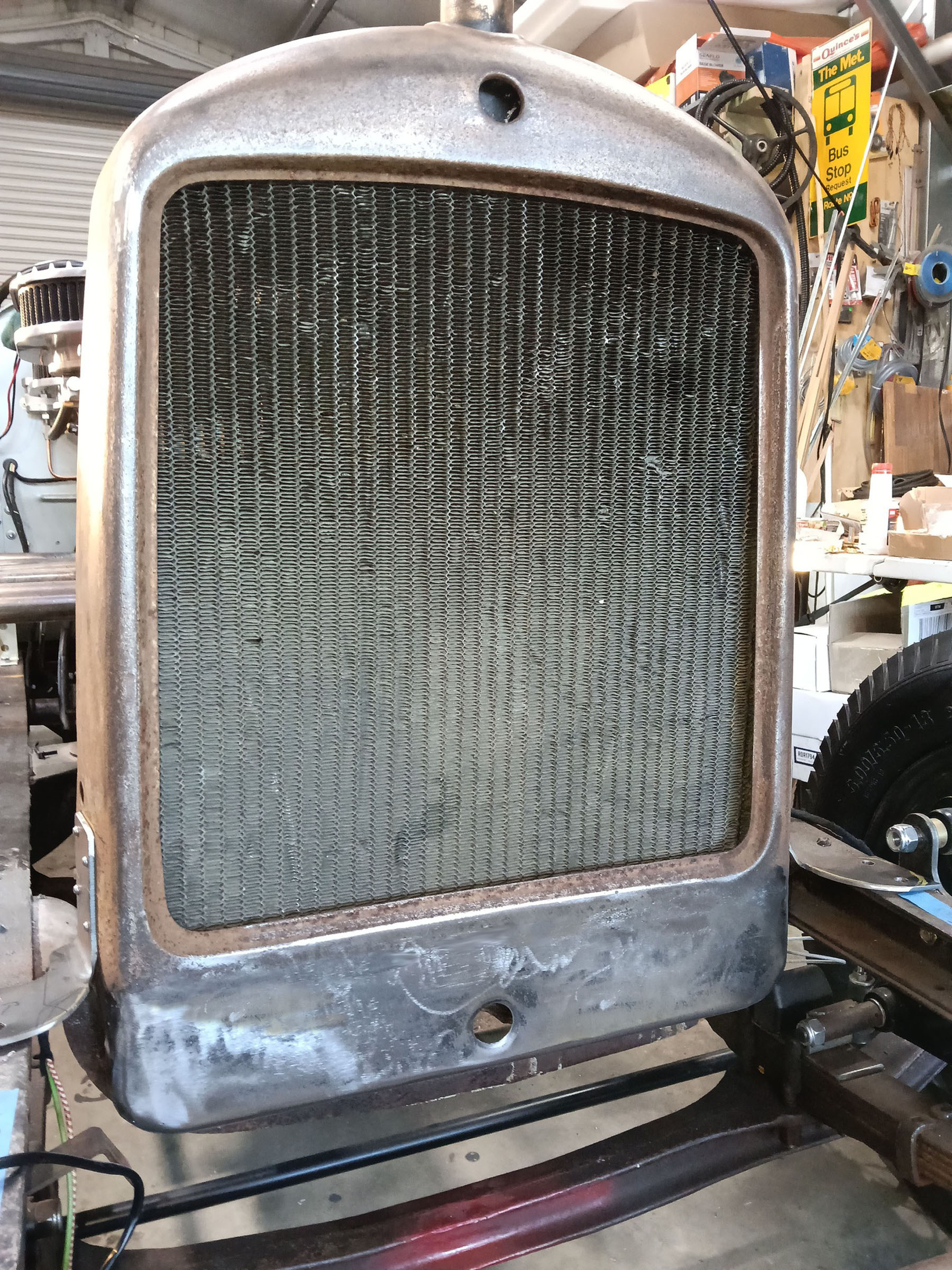
Radiator
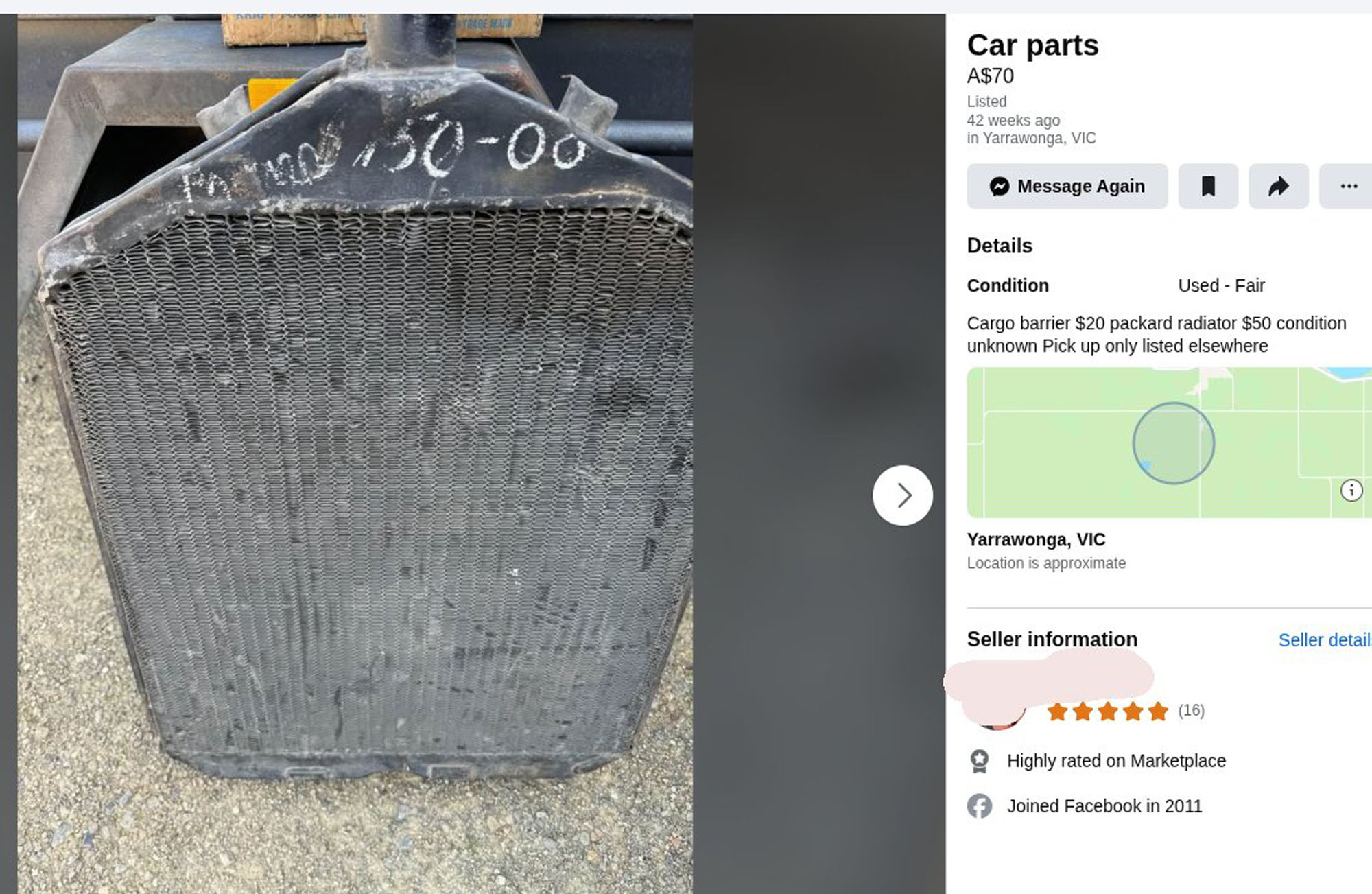
A lucky find on local Facebook Marketplace, just 10 minutes down the road. 1928 Packard Radiator for $50 - WTF , The seller said his father paid $50 for it in the 1970's as a spare for his Packard and its been in storage for 50 years , still has the original $50 chalked on it & thats all he wanted. What a deal.I had to change the bottom outlet to the right side to suit the holden water pump so I could inspect inside , it appears free of rust & scale.
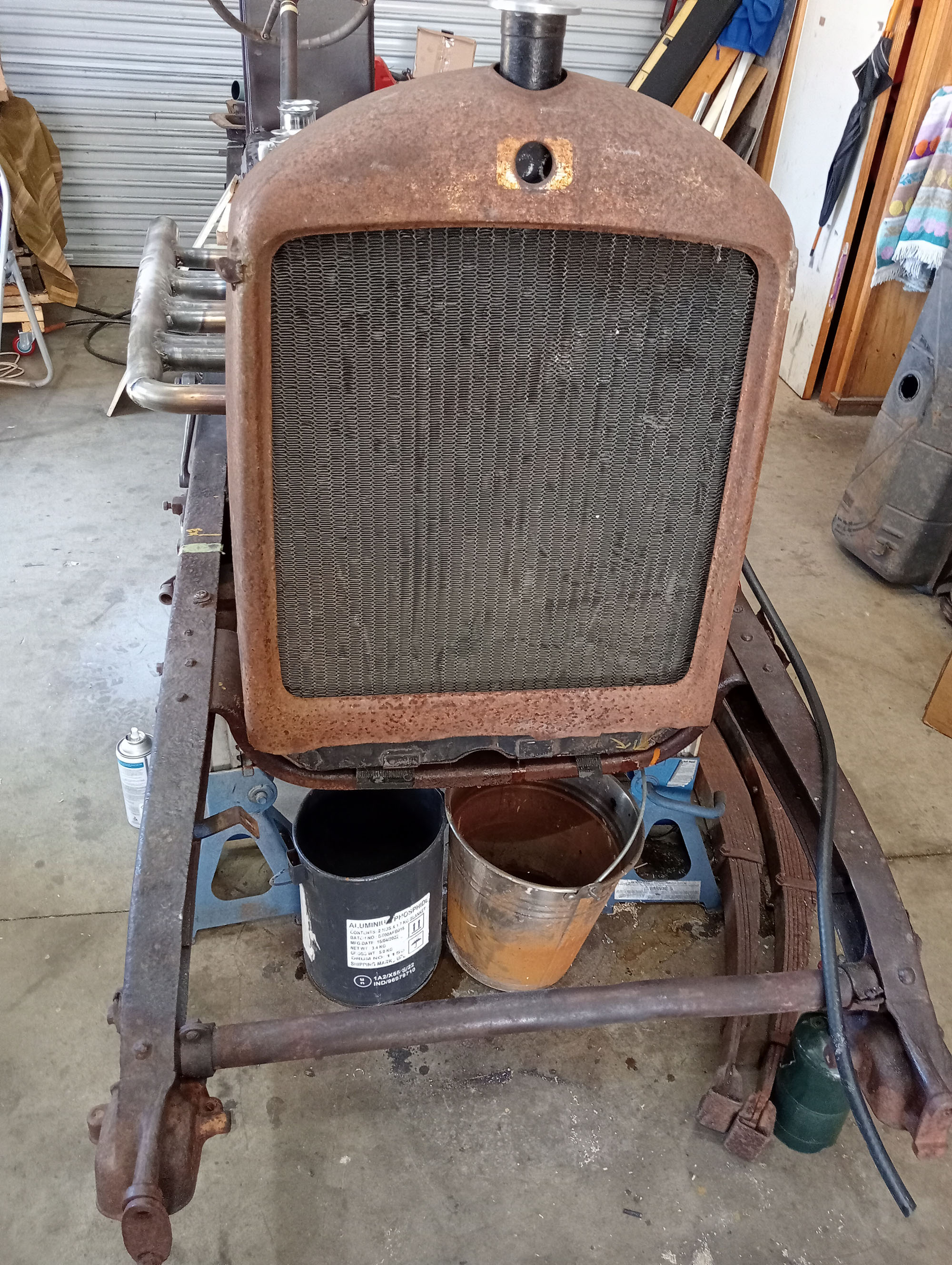
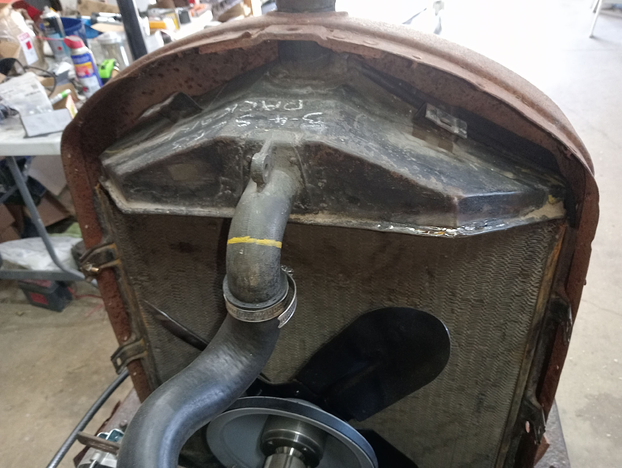
Radiator sorted, but I needed a shell and not confident about my sheetmetal skills to make compound curves I bought another radiator and shell from Marketplace, Seller said it was on a Dodge but he didn't think it was original to the car . The Shell fits nicely over the Packard radiator , Turns out its from a Jewett , quite a rare car in Australia, its a big American car from the late 1920's which evolved into the Graham Paige.
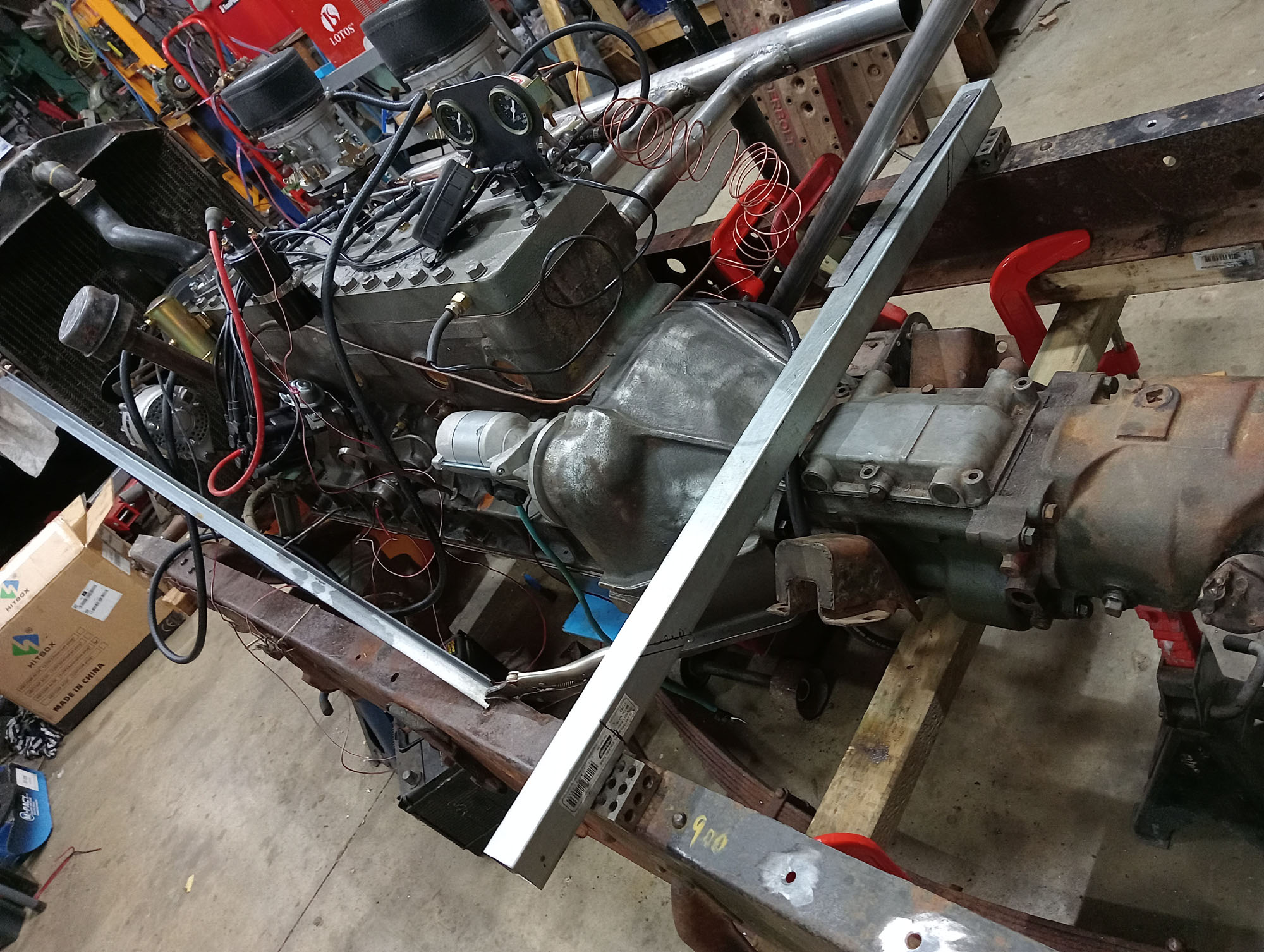
3 months progress
I gave myself 10 years for this project, at the rate its coming along it will probably be done in 3 years.
Here we are at 3 months, The engine and gearbox are mounted in chassis, we have a radiator & I can give the engine a proper run . Its running much better than the first start video as it had a few inlet manifold leaks and distributor timing was out a wee bit. I have all the tappets at 12 thou so they are a bit rattly, a noisy tappet is much better than a leaking valve. Once the engine has had a good drive I can set them & quiet them down.
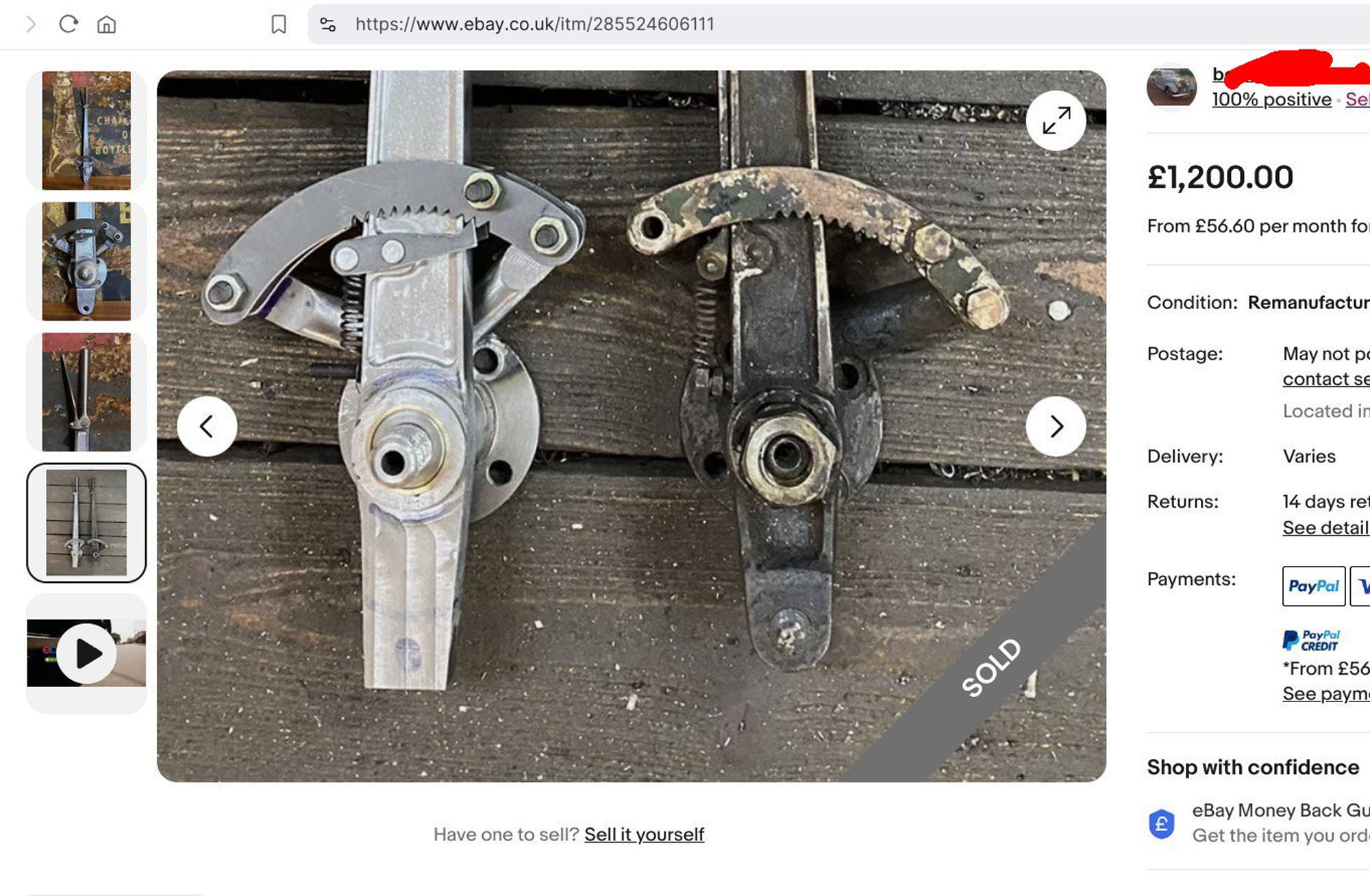
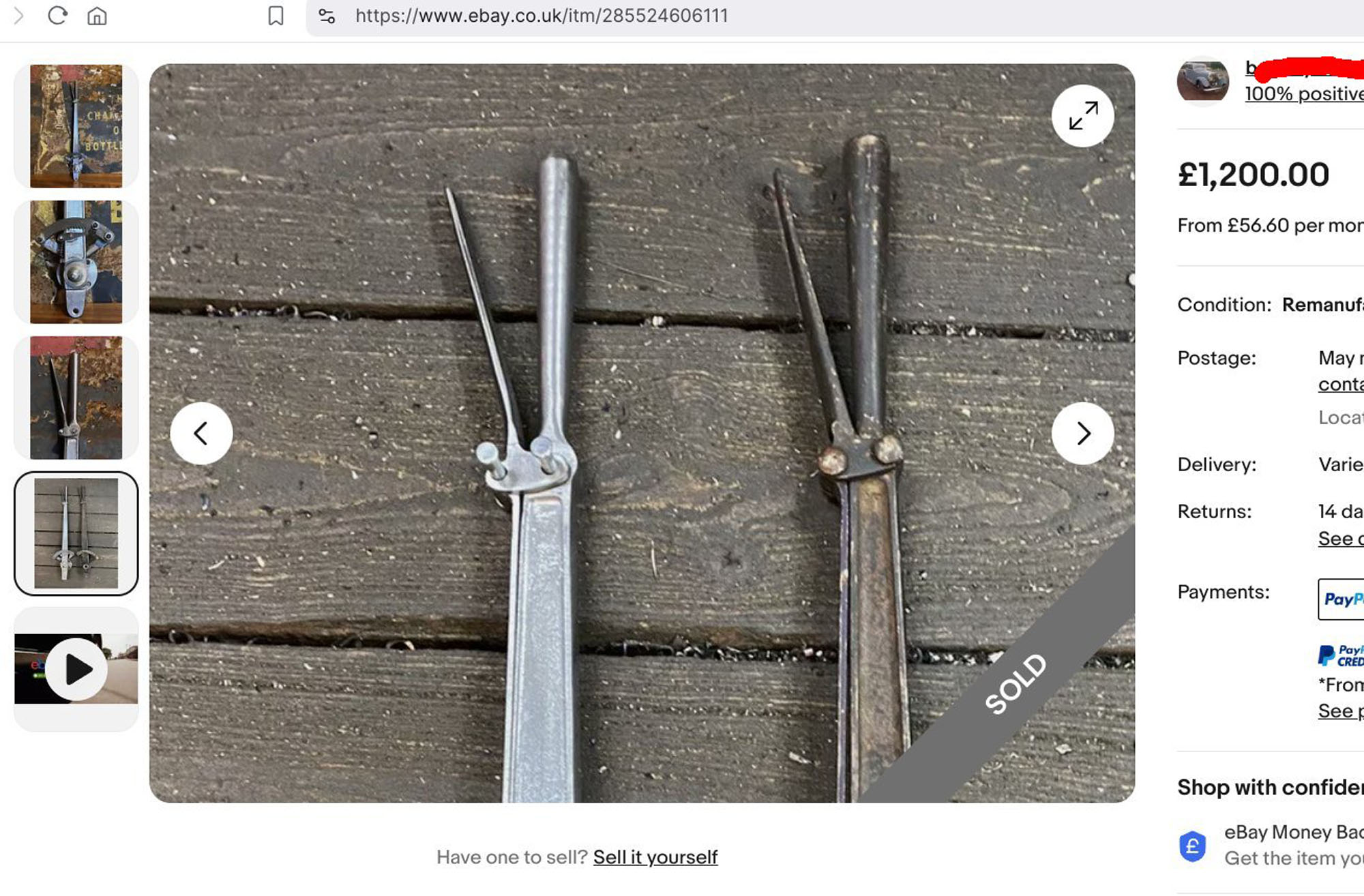
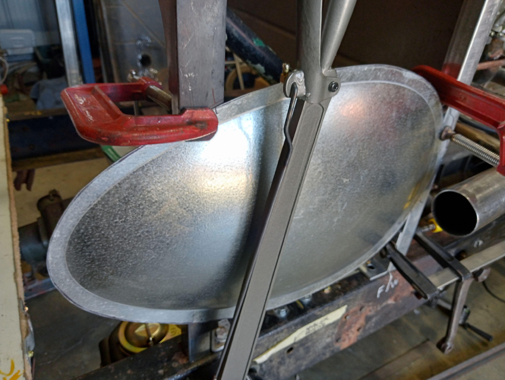
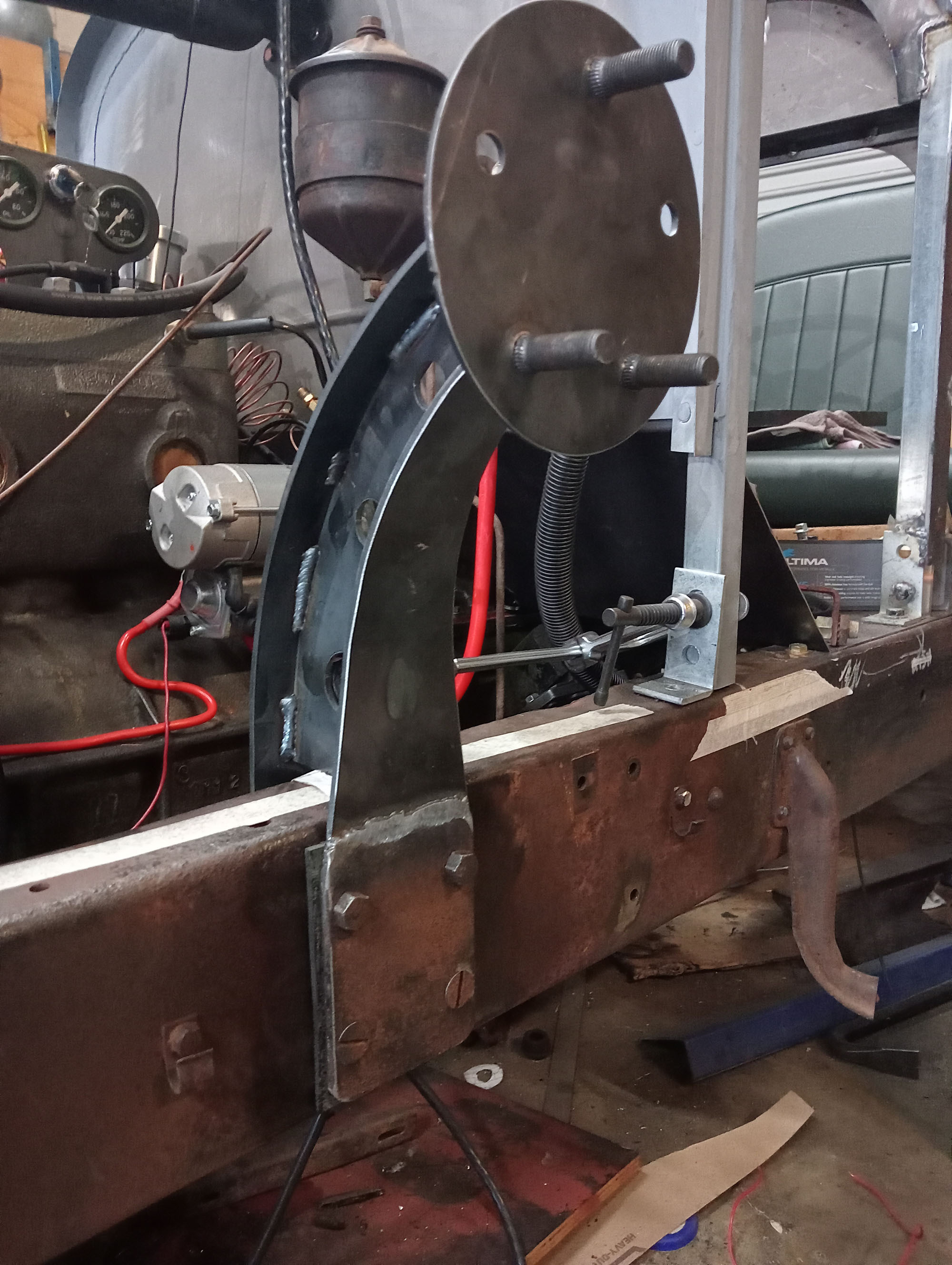
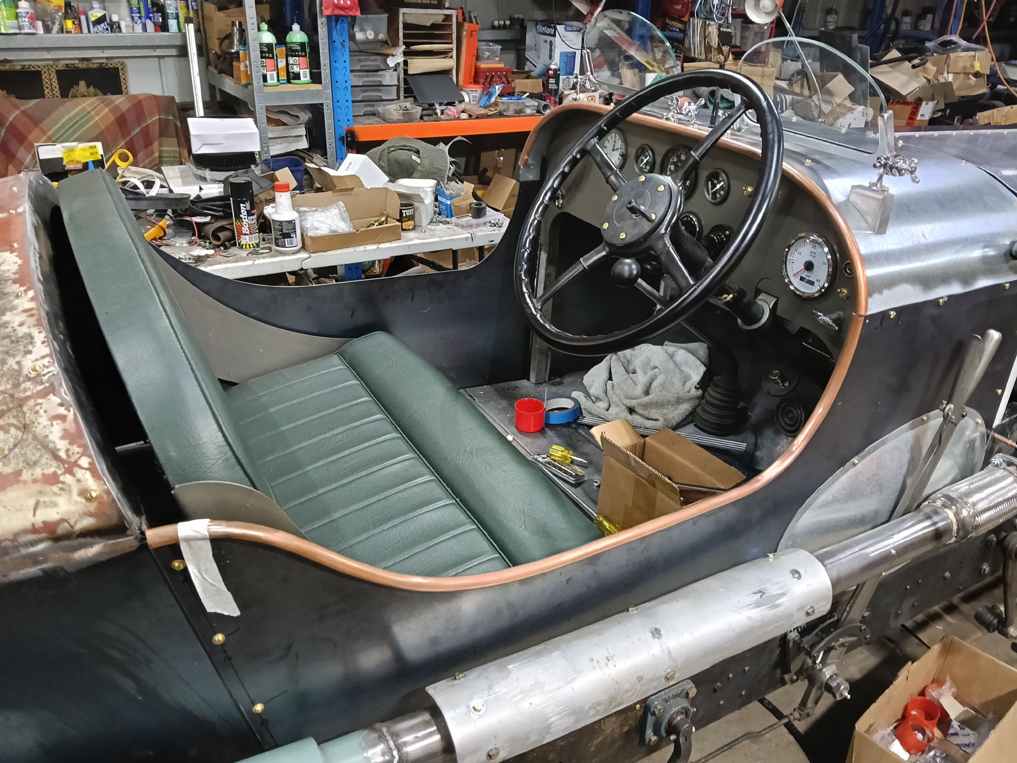
Handbrake Lever
At this point I have a clear idea of what I wanted the car to look like, 2 seater , boat tail, open wheel speedster with external handbrake lever and exhaust along the side. The body sides will be vertical & in line with the chassis edges so that gives me a seat width of about 36" , a bit squishy for 2 bums, similarily there will not be much leg and foot wiggle room , thus an external handbrake is a necessity rather than just fashionable.
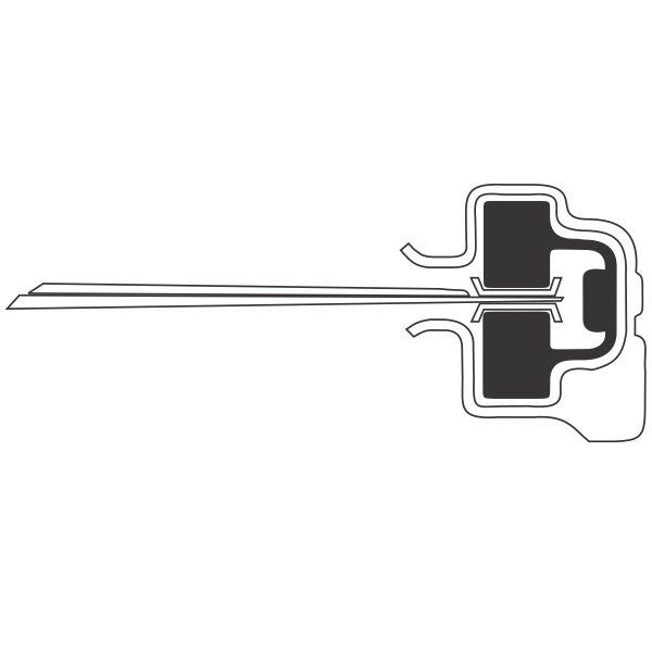
The Bentley of the day had the exact handbrake lever I was envisioning and one appeared on eBay UK for £1200 , yep AU$2500 for a flipping handbrake lever. Many thanks to the seller for posting nice detailed pictures as I was able to copy into my CAD software and had the flat pieces plasma cut . I machined the end of the handle on the lathe and made the release catch from a piece of exhaust pipe. I used a VW stub axle for the pivot . The whole shebang cost me less than $100.
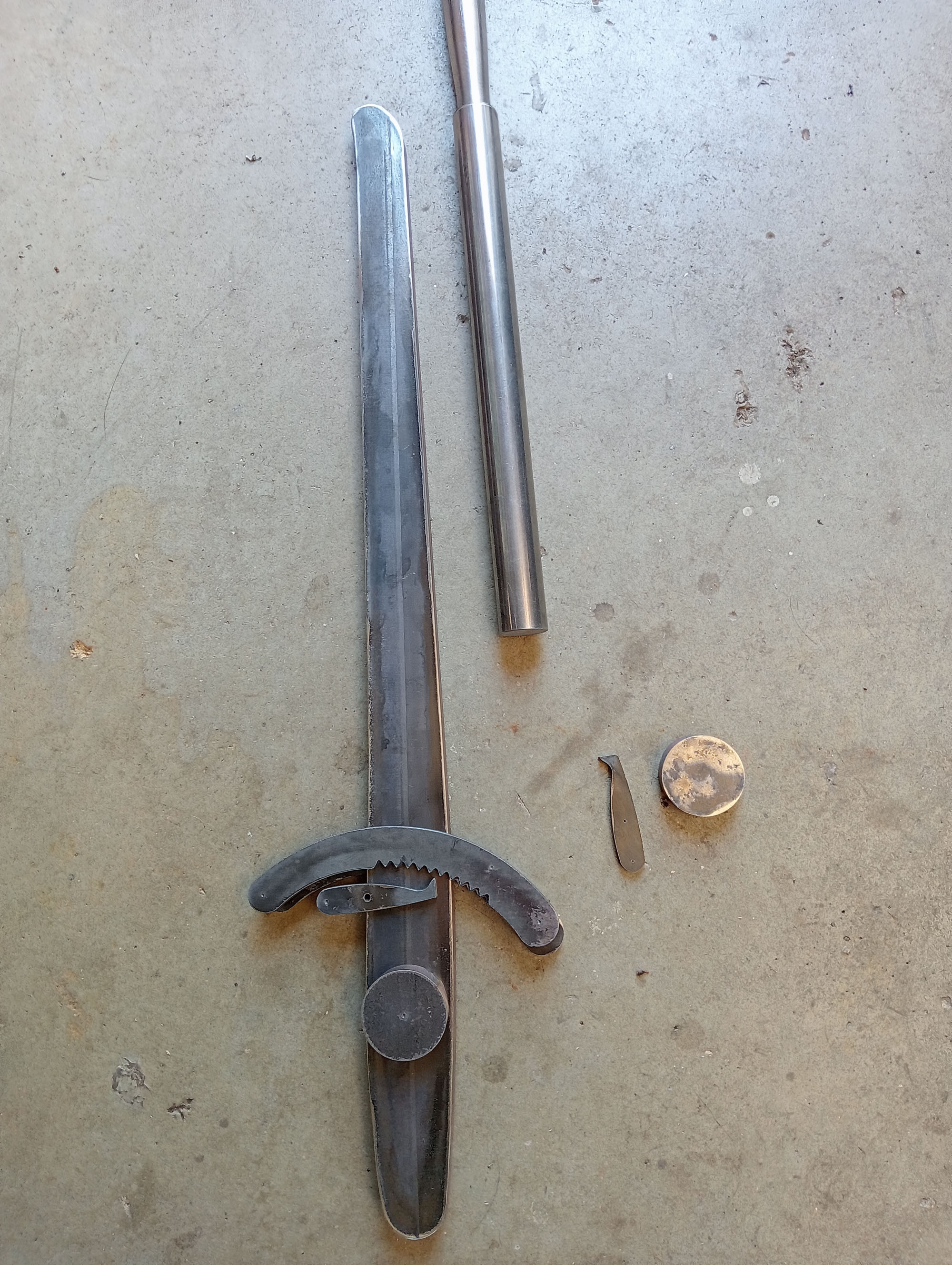
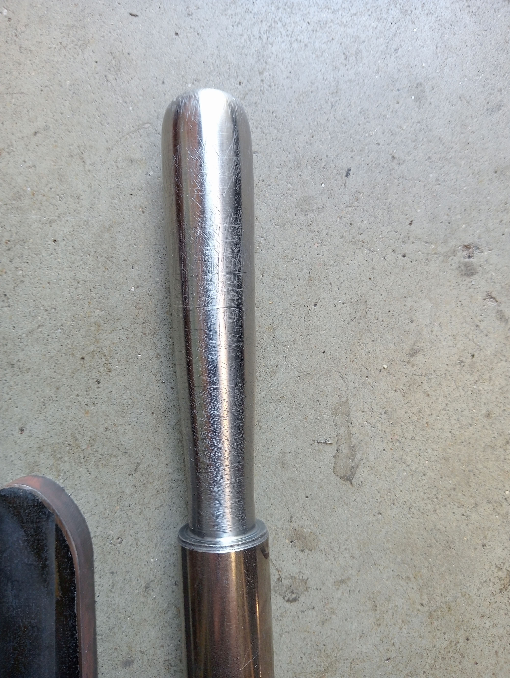
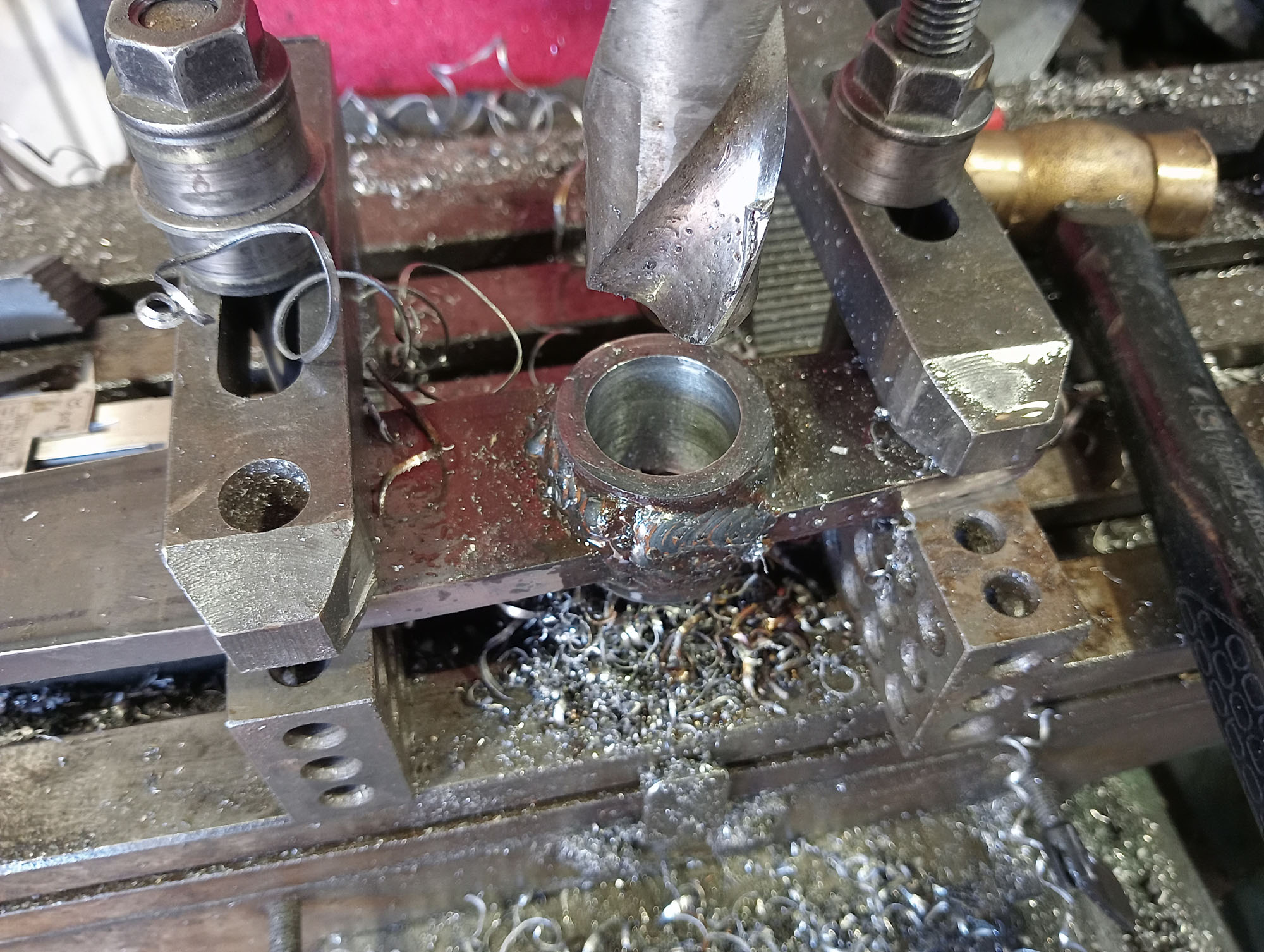
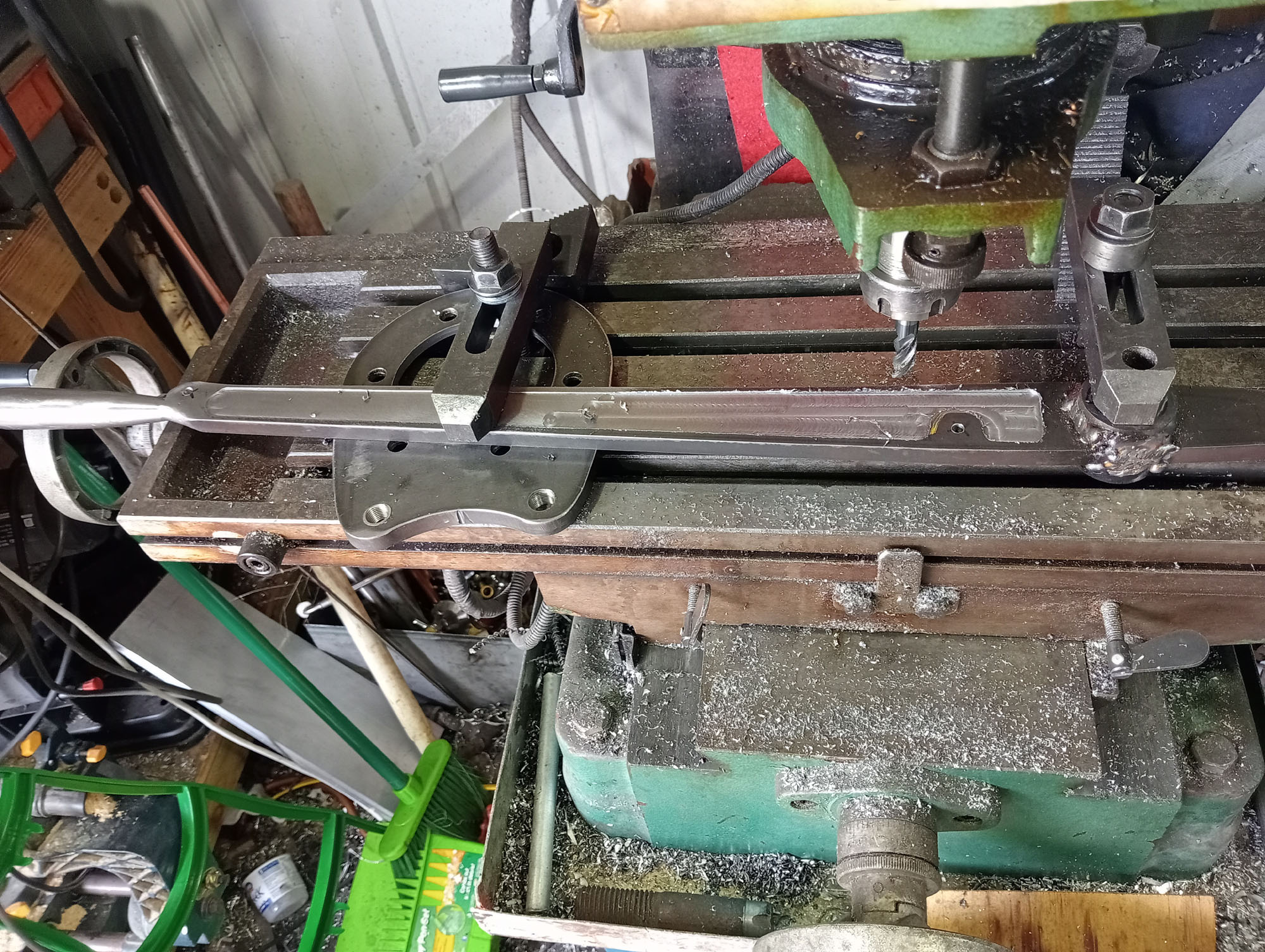
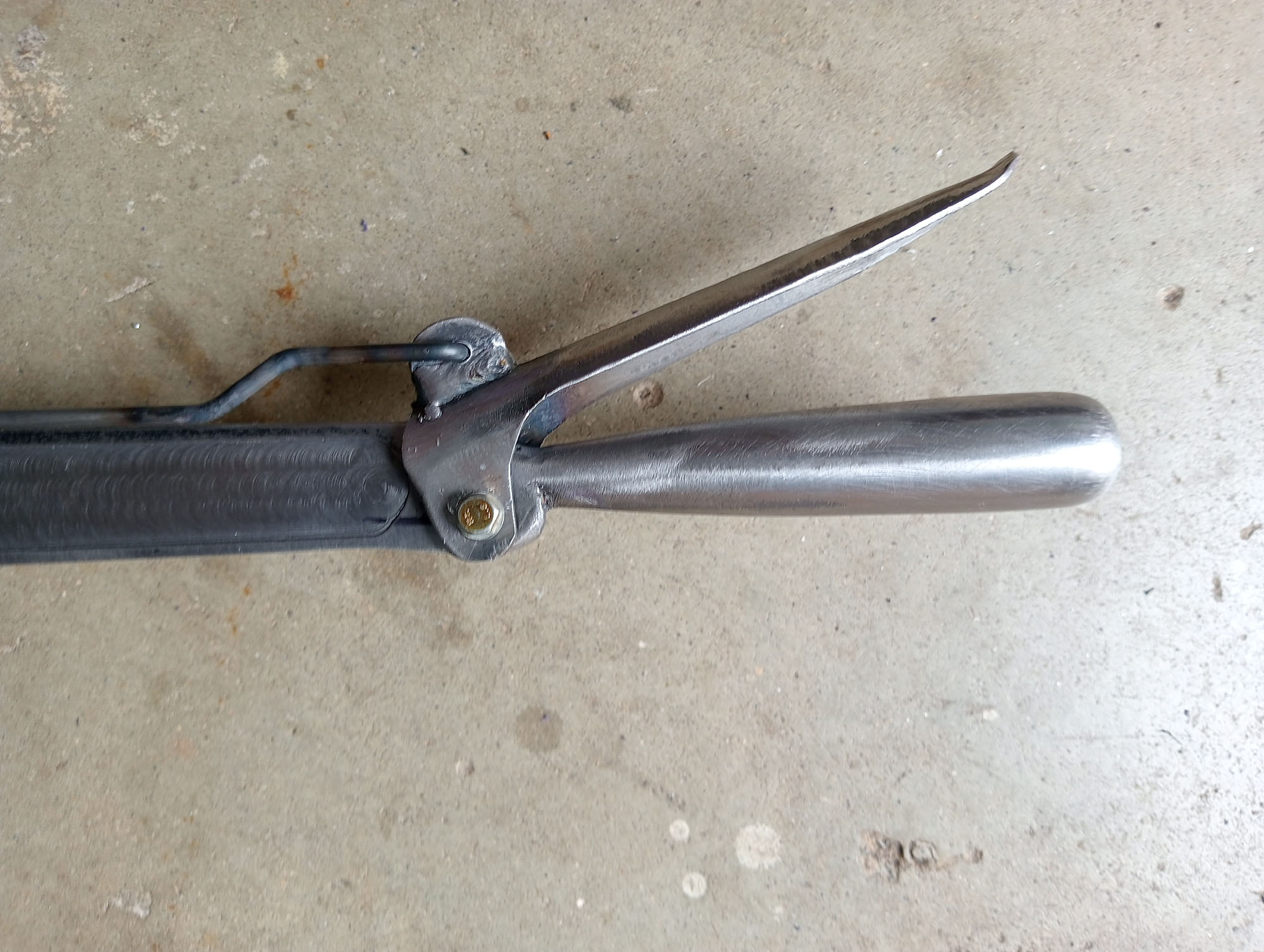
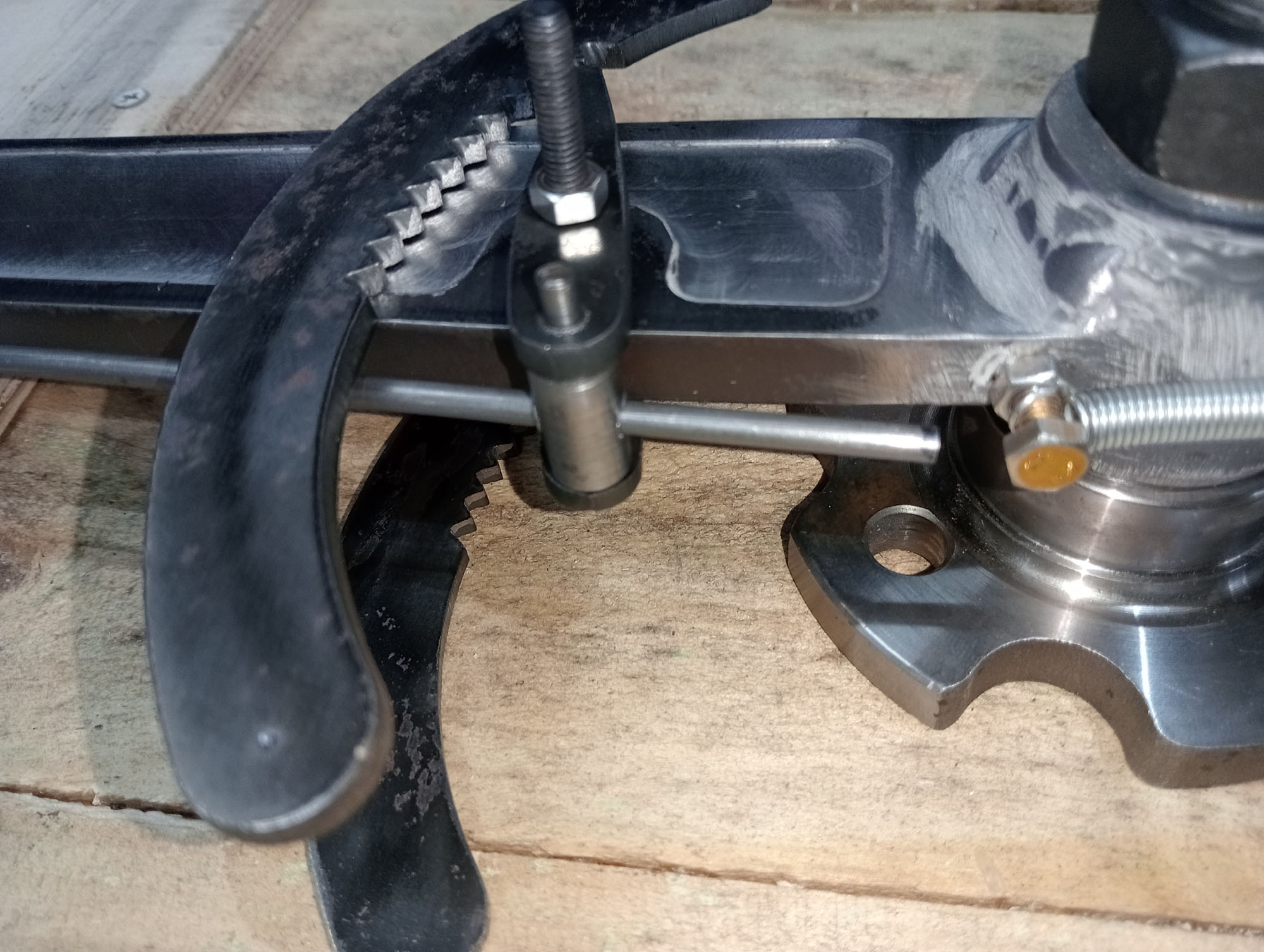
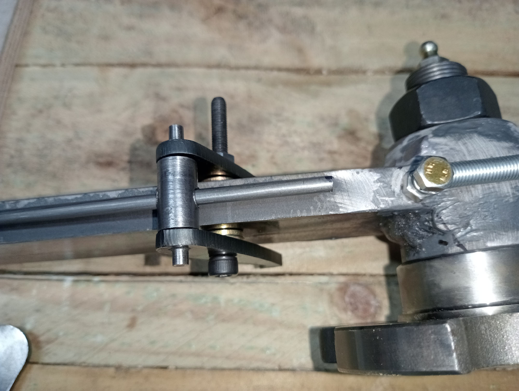
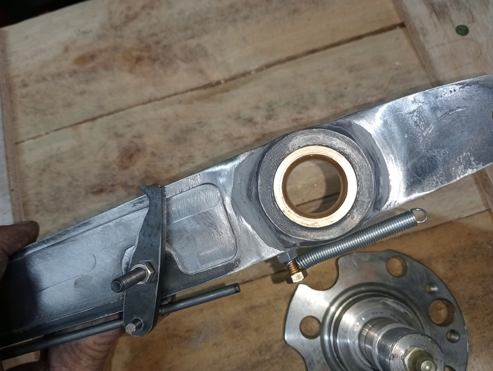
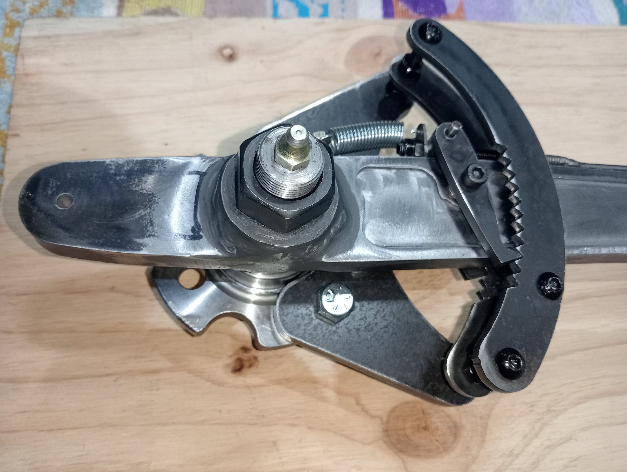
As a side note, when you plasma cut steel, as by-product of the cutting process the edges are heat treated, sometimes a nuisance especially if you need to drill a hole larger - you need an expensive carbide drill, but in this case a bonus as the ratchet & pawl teeth are toughened.
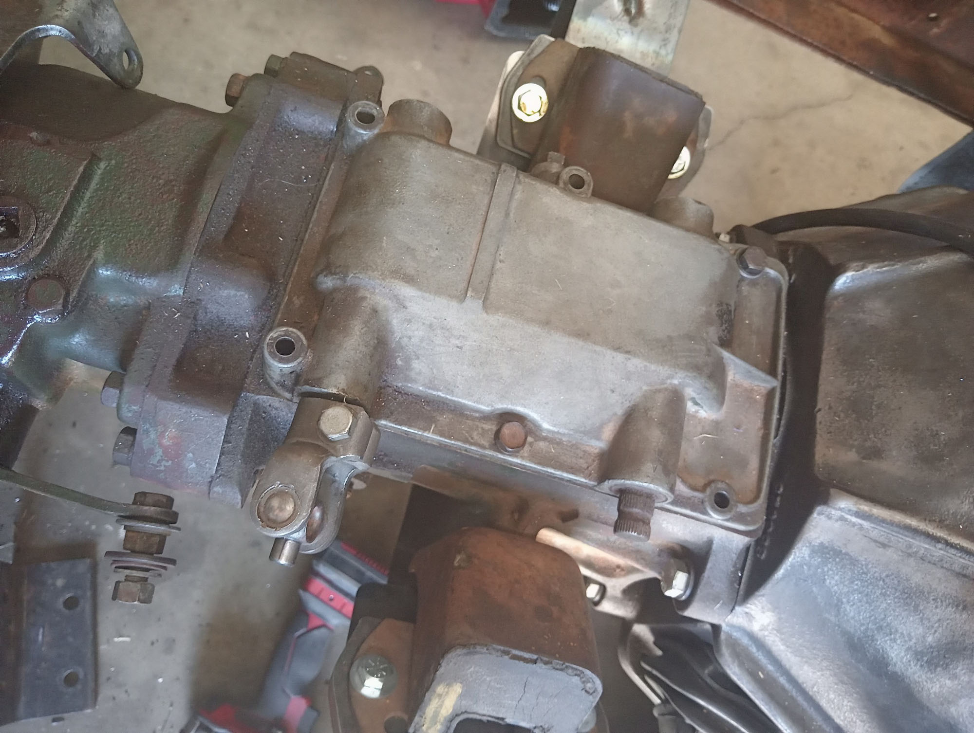
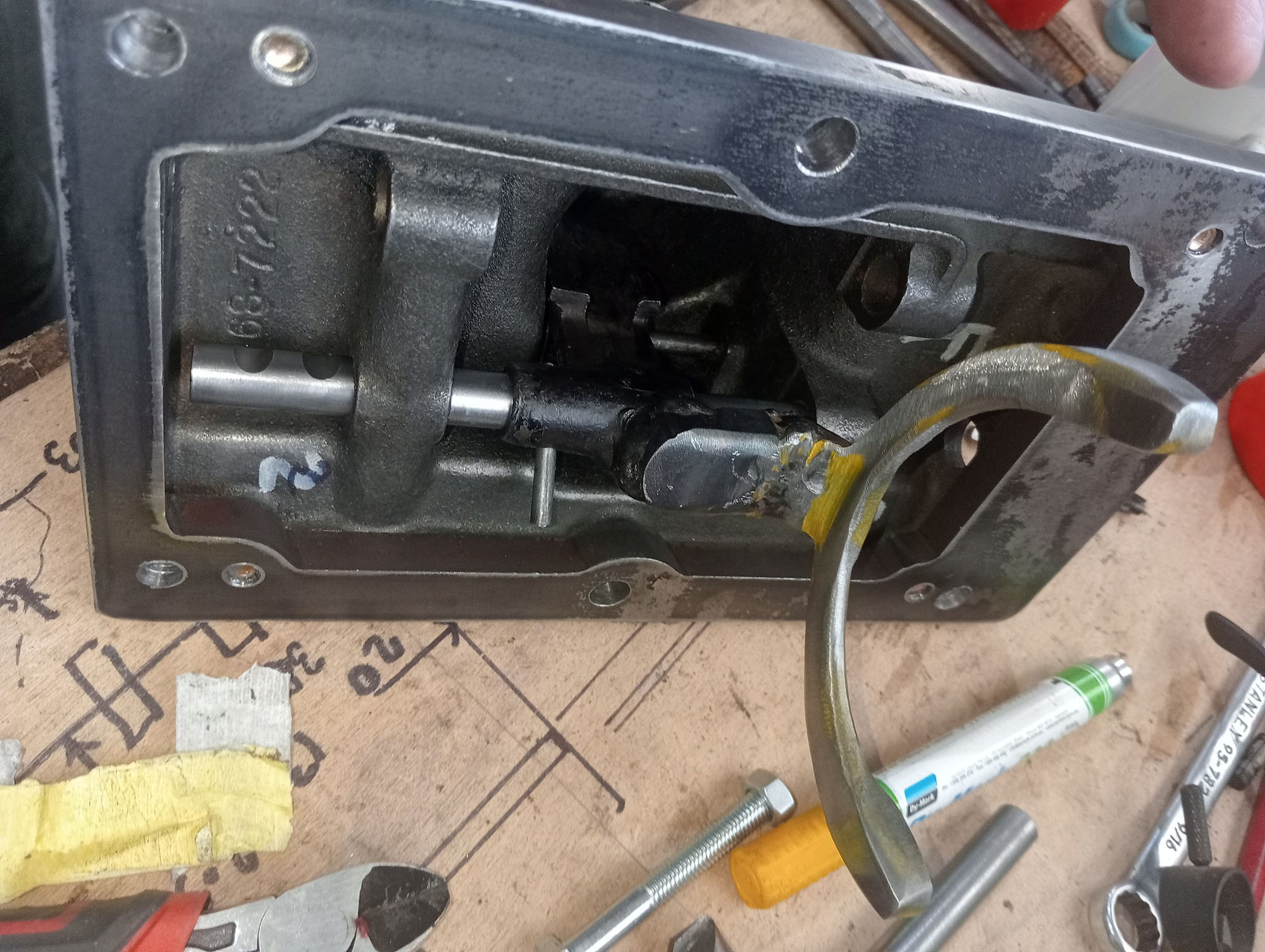
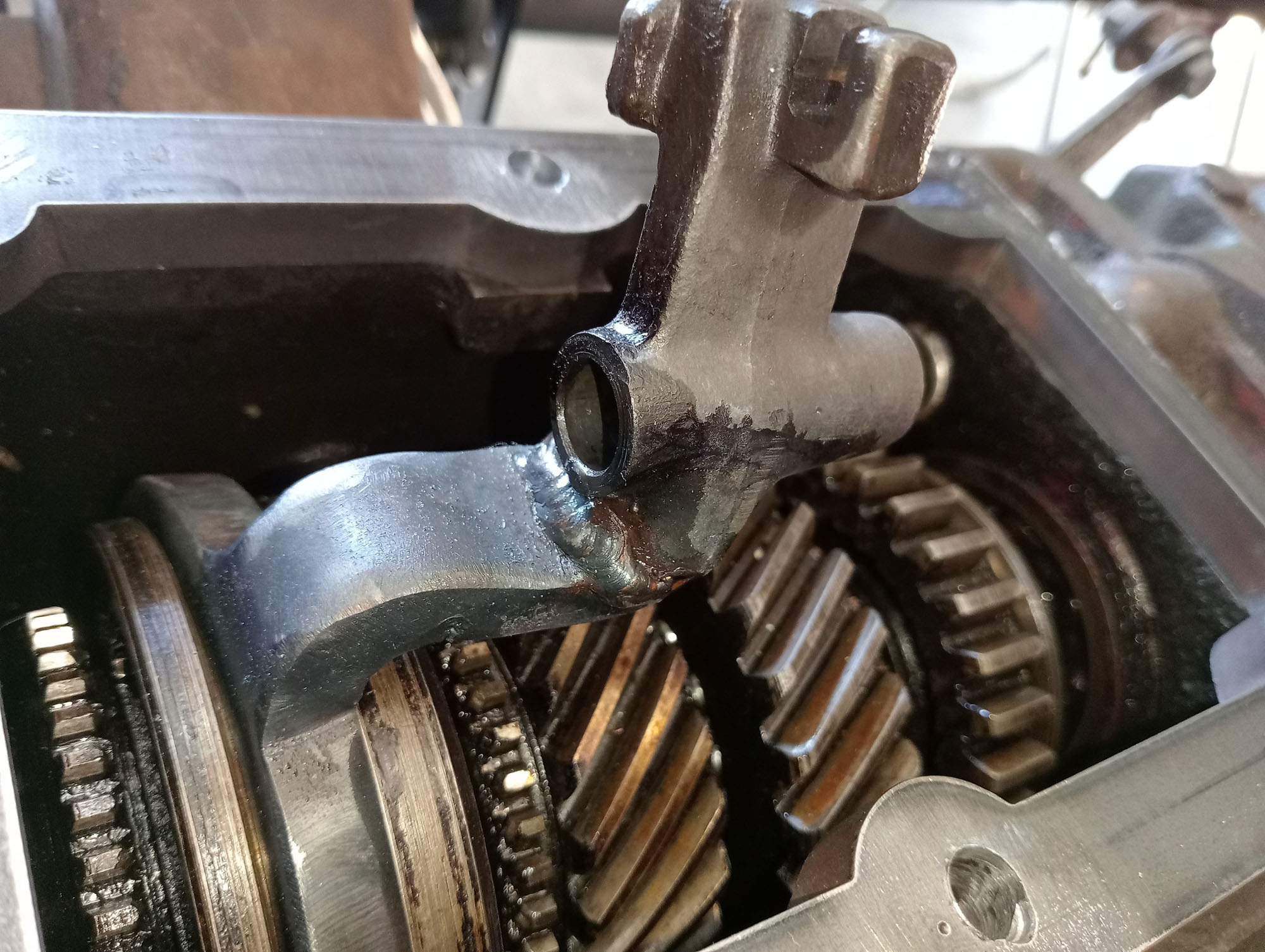
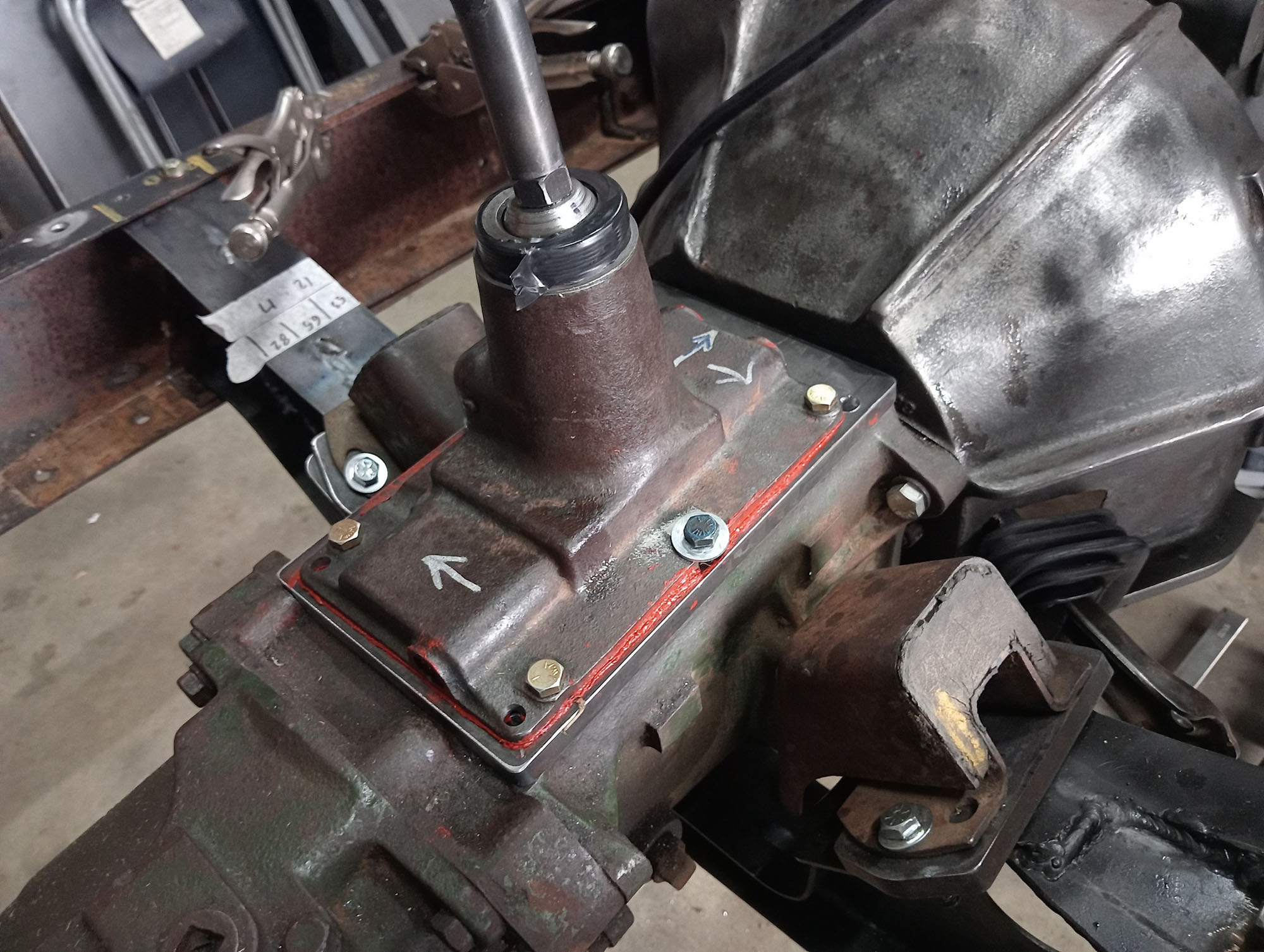
Gearshift Lever
The 3 Speed Packard gearbox I am using in this build is from a car with a column shift, thus it has a lid with side shift linkages rather than a shift tower or top loader style. A Speco or Aussie 3 speed floor shifter could be adapted but it will necessitate a big lump in the floor to cover the linkages and the realestate is as at a premium so I decided it best to find a top loader lid to fit. I drew a blank at finding an earlier Packard shift tower, most of them were used up in the pre ASRF hot rod days.
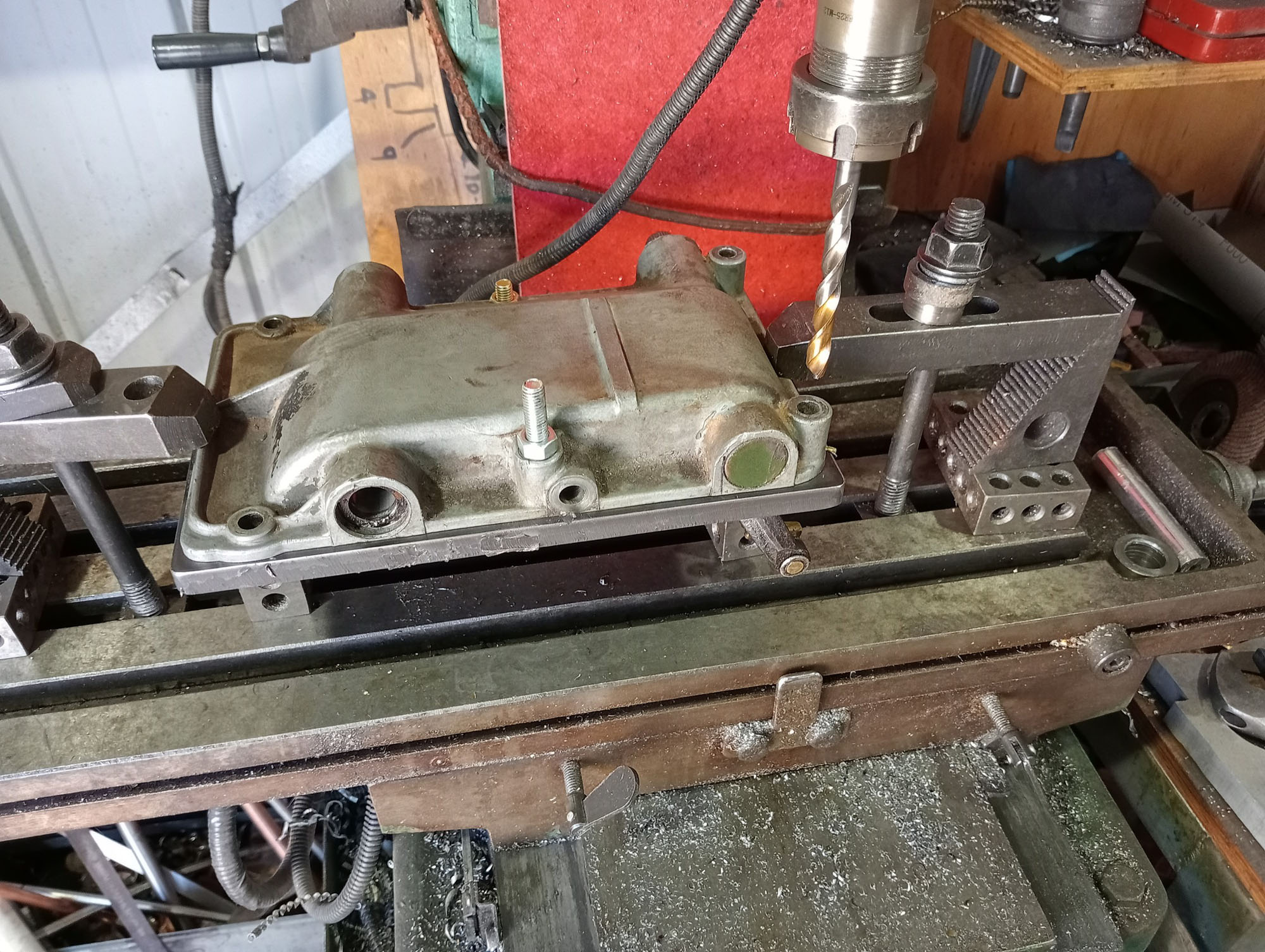
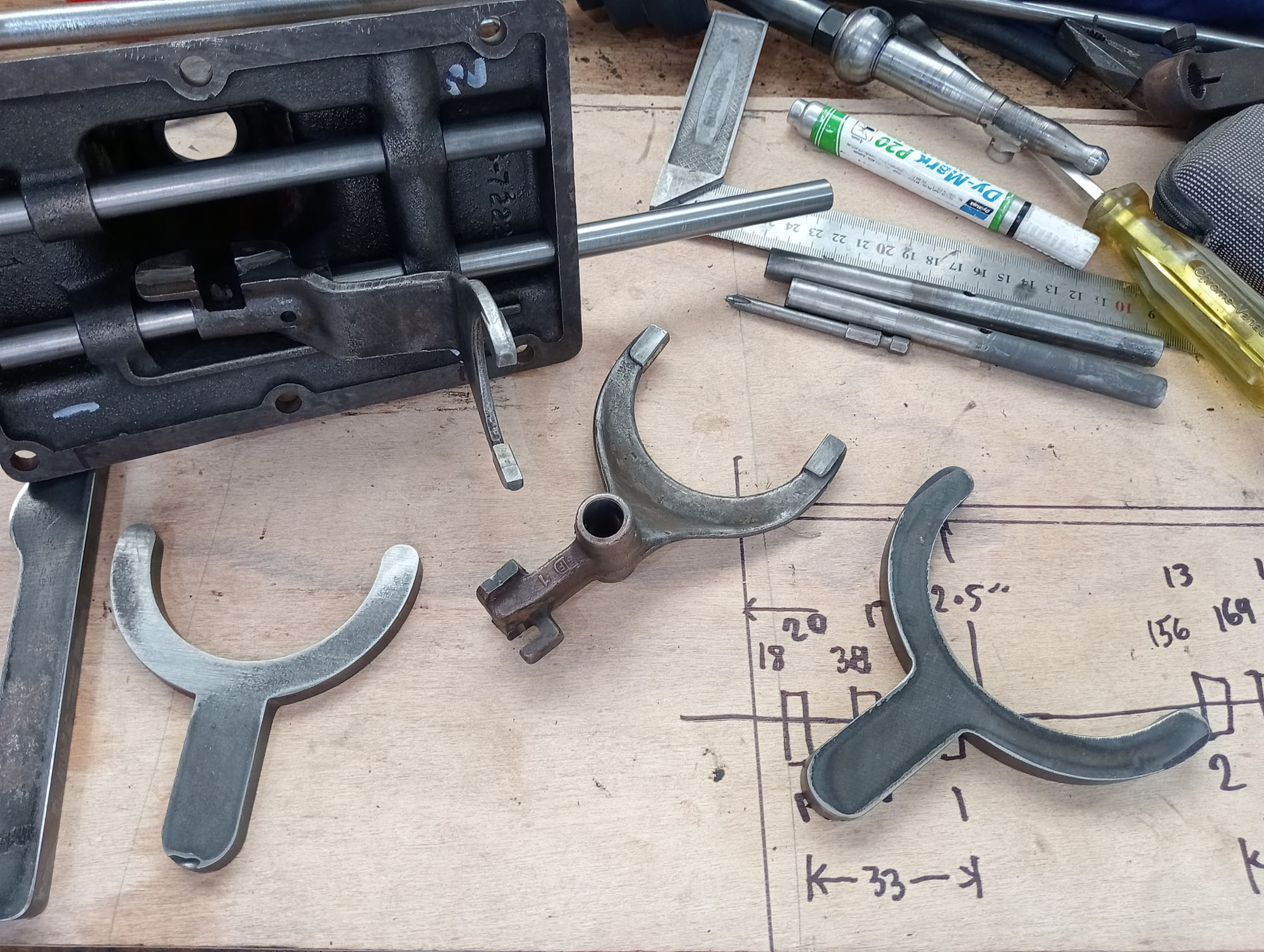
Not a straight forward job. The old adage measure twice cut once, for me means measure four times, then mix up the numbers, mill the detents in the wrong place, weld a bit more metal on & cut it again, , repeat . It needs to be right, because If its as little as 0.5mm out of whack, it could jump out of gear... I saw this '36 Ford shift tower on Marketplace for $60 so grabbed it, I have heard they can be adapted , but no details or photos found so I'm reinventing the wheel.
I made a adapter plate from 12mm as the Ford lid is smaller than the Packard hole. Made new shift forks & grafted the new 2-3 fork onto the Ford selector needed checking for fit, grinding to shape so it did not interfere and rechecking was the most time consuming part of the job. Lid - on Lid -off about 47 times. The Ford 2-3 fork was close to fitting the Packard 1-R slider so I adjusted it and grafted it onto the Ford 1-R selector. Then made new selector rods as the Ford throws are wrong for the Packard box. That needed to be millimeter precise .
I had to make a new Gearstick, these early Ford gearsticks are about US$250 so about AU$600 by the time they get here. I made it from a trailer stub axle - nice bit of steel , not going to bend in a hurry. It was easier to make it in two pieces with a lock nut, bonus is I can fine tune the position Seems to work OK & no jamming sitting in the shed.
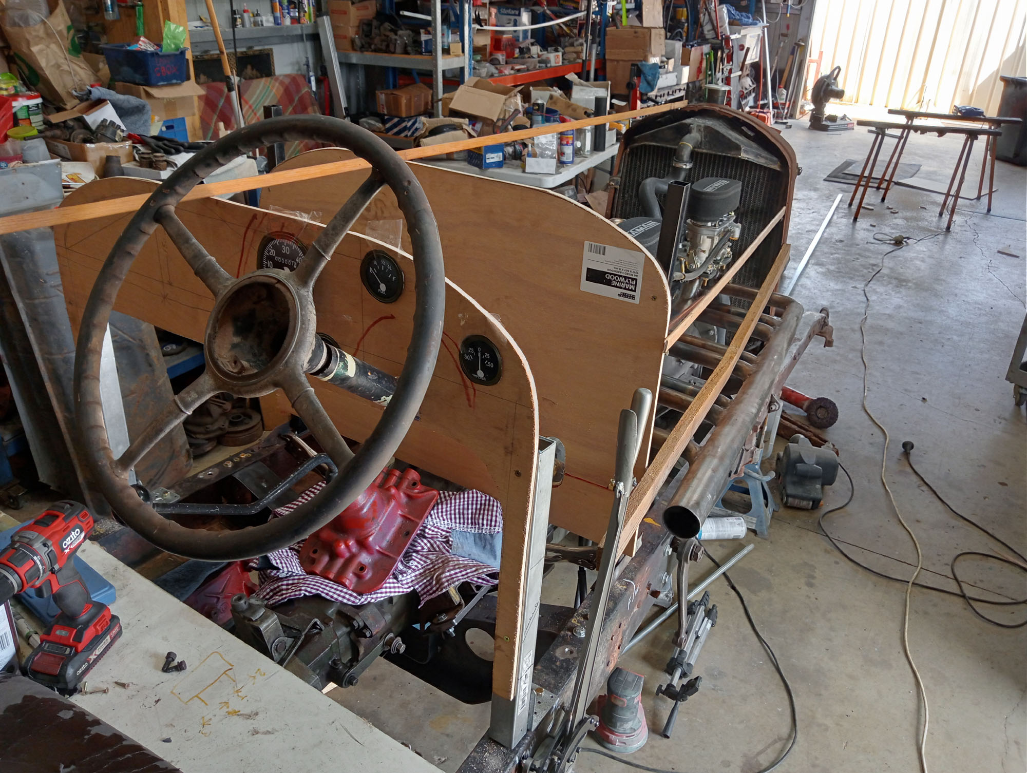
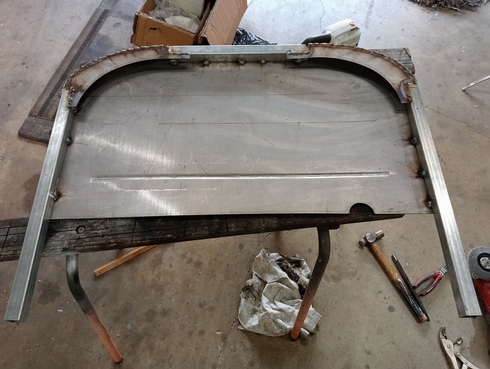
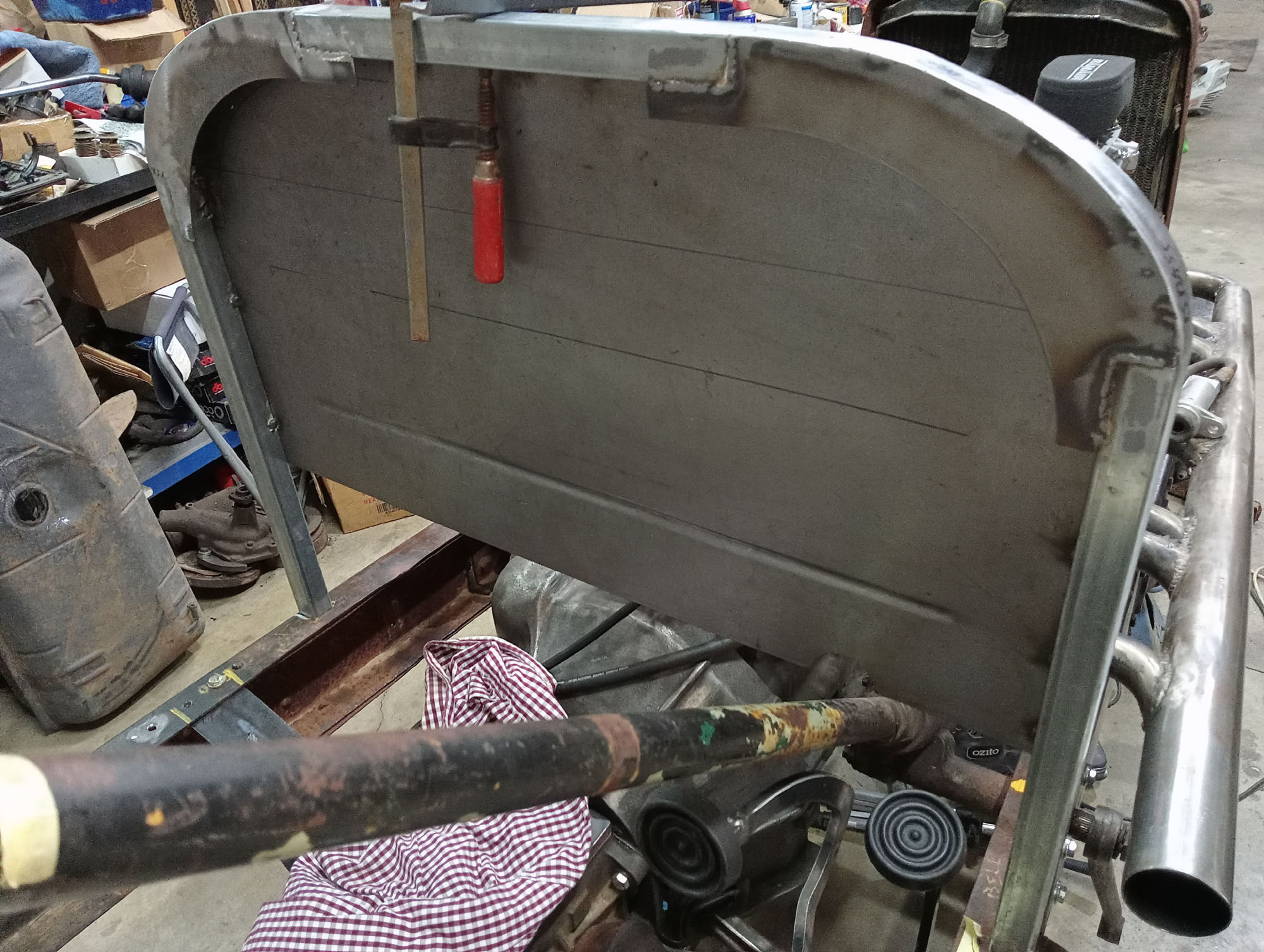
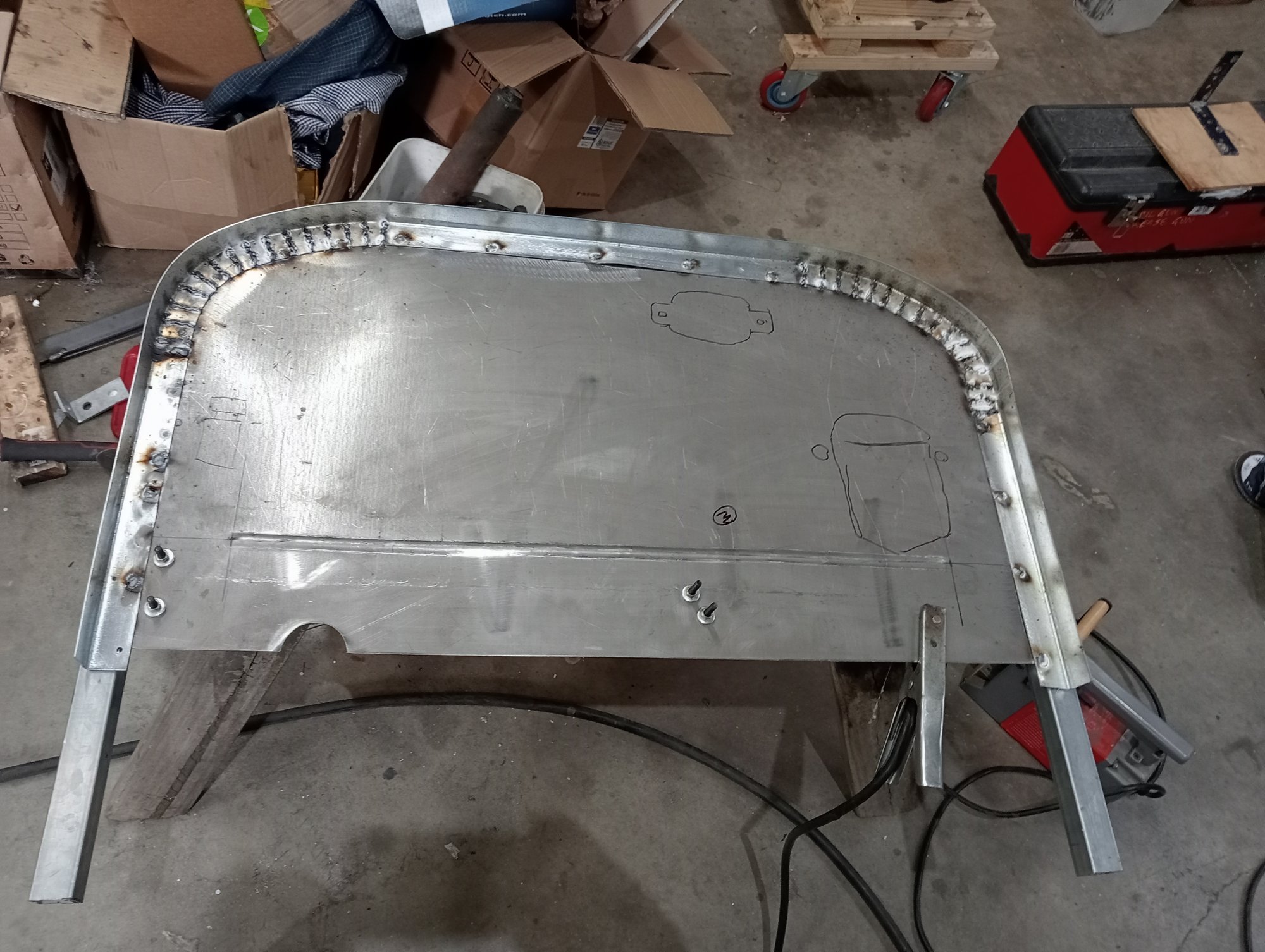
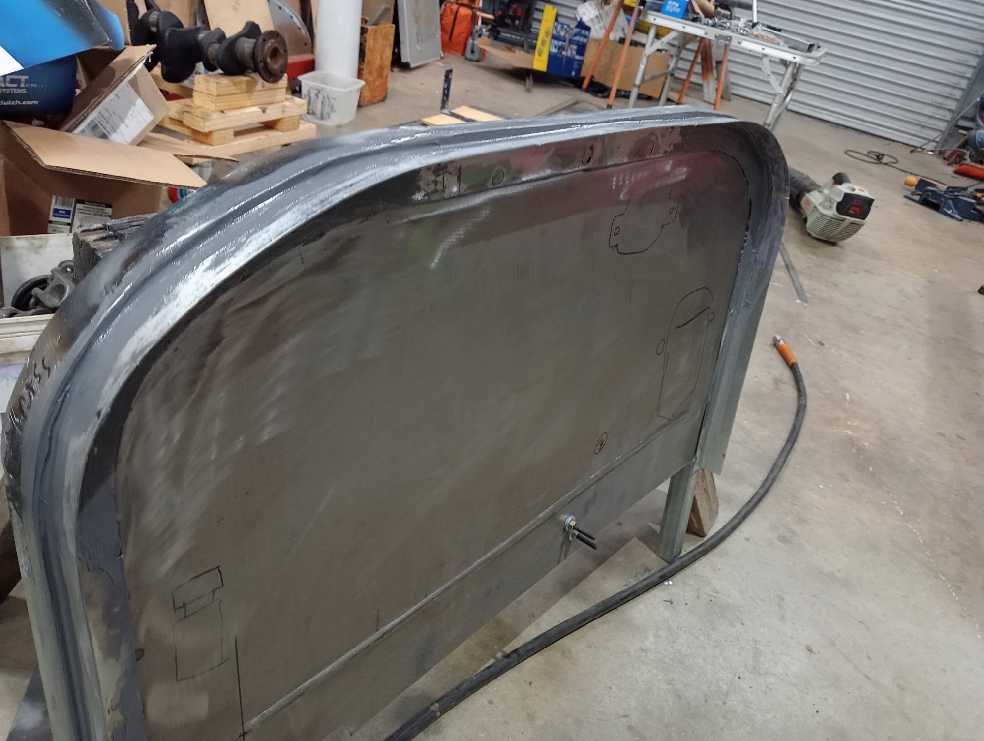
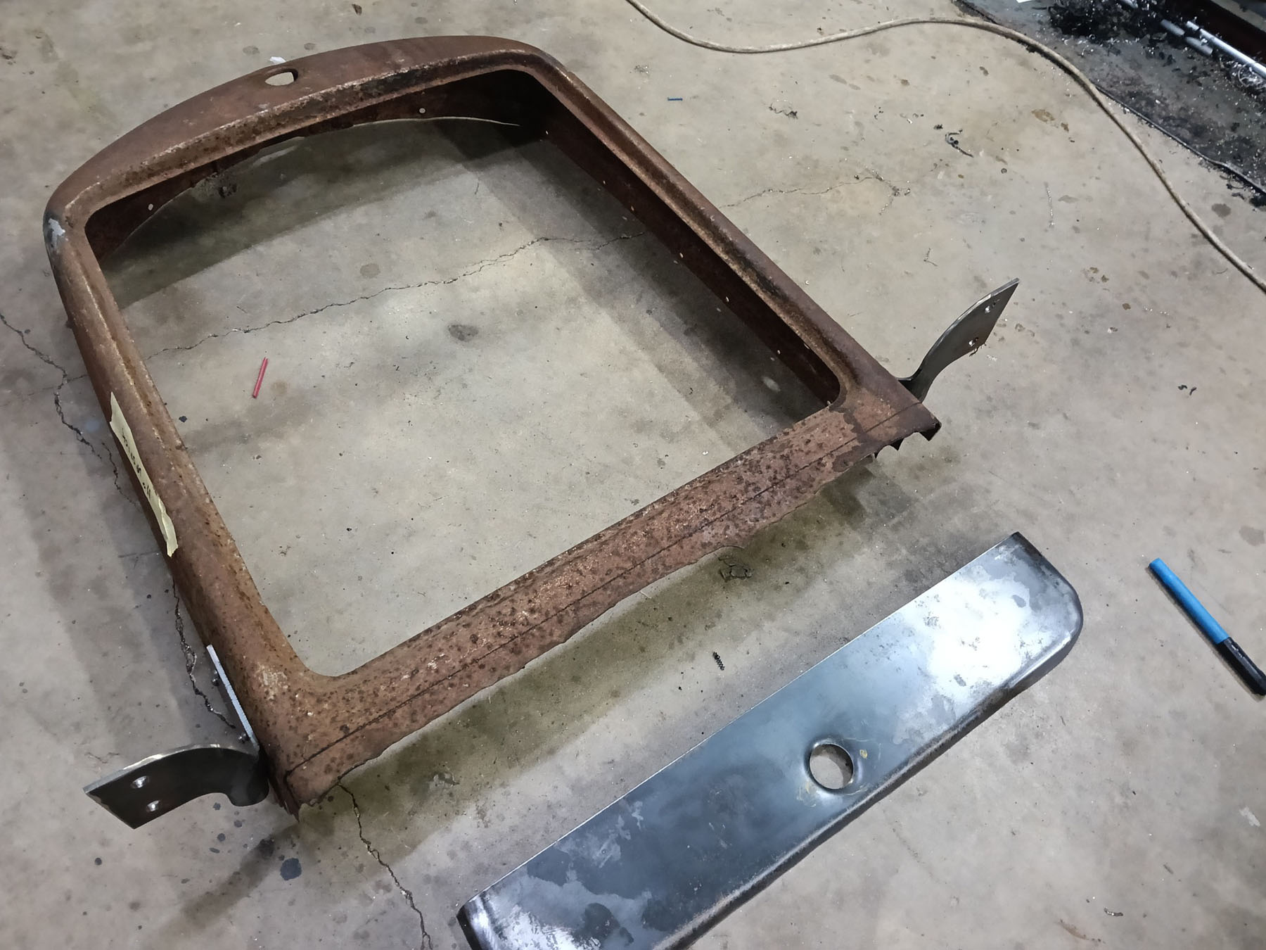
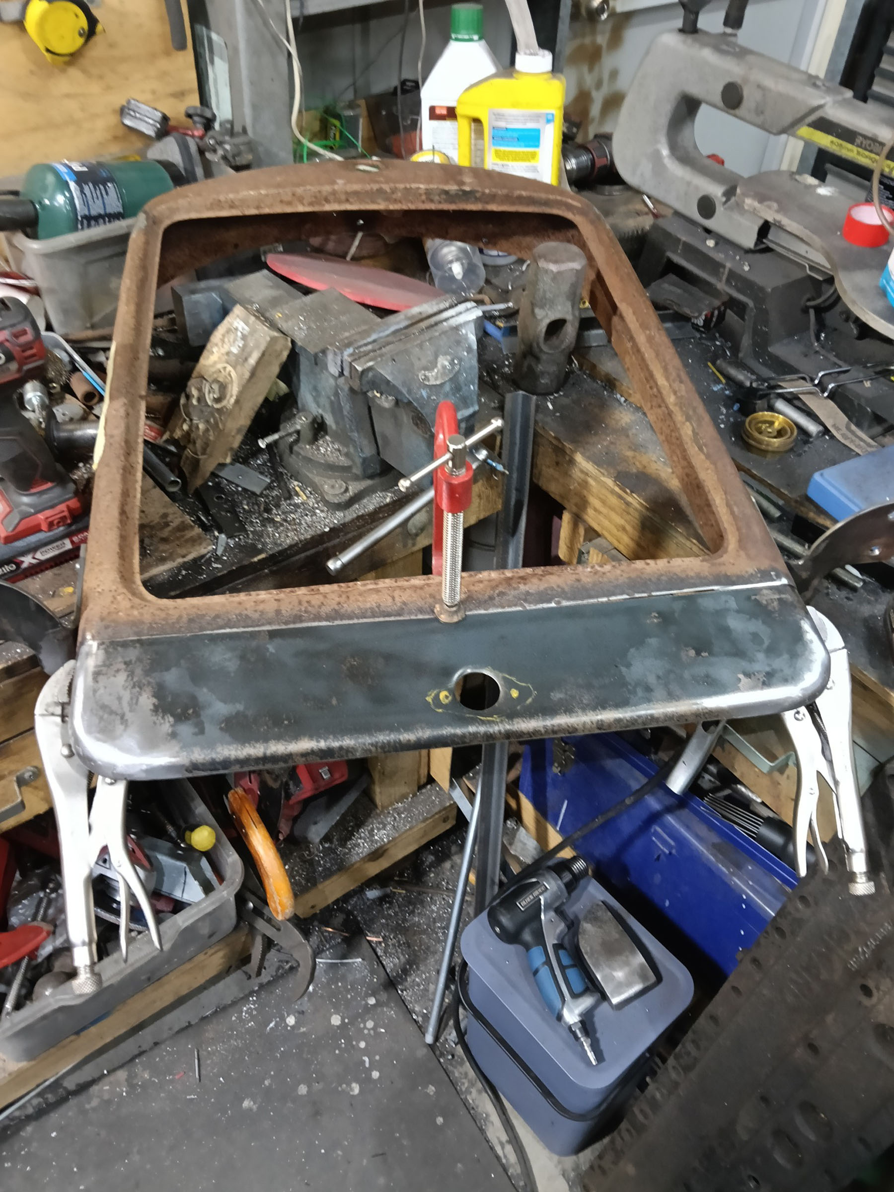
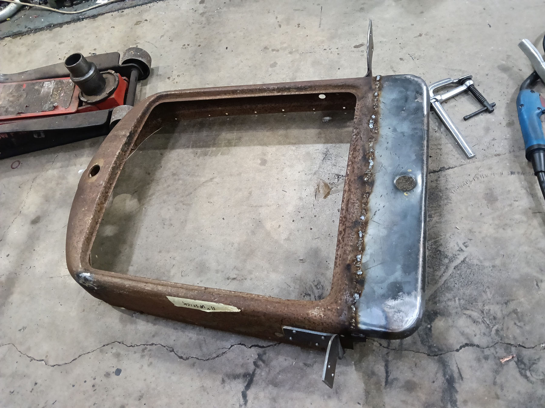
Firewall / Scuttle
I first made the firewall & dash from wood templates & adjusted the height to organically match the radiator shell, The rounded curve at the sides matches the radiator shell. I then copied the template into CAD & had the parts plasma cut so that I could fabricate the firewall.
Hydroform a body blister
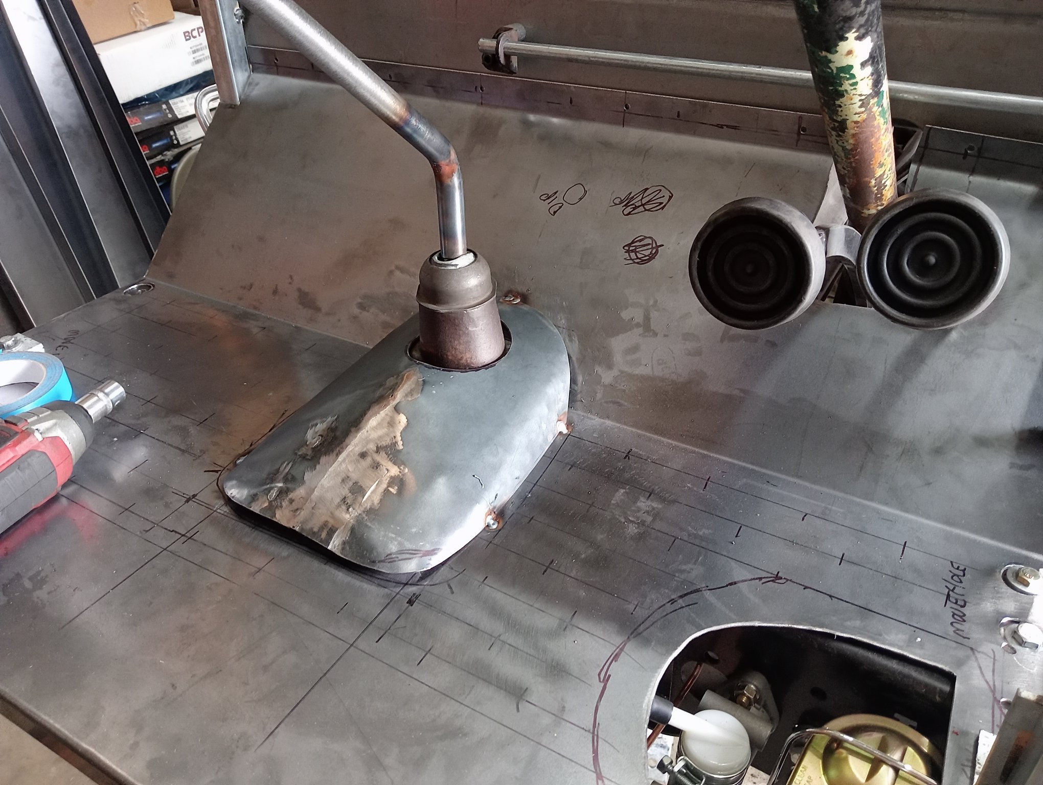
As mentioned earlier there is not much interior real estate, Foot room is at a premium and the Brake pedal location does not leave much room for a throttle pedal. This is the problem with a 'design on the fly' project where you don't think of every detail at the outset, instead it evolves.
In this case the throttle pedal is hard up against the right side of the footwell, so I am using a sheet metal blister or bulge to give some foot room.
Rear Axle
The rear axle choice for me was a compromise. Ideally I wanted a prewar rear axle. The Packard of the era my engine & transmission came from had diff ratio options of of 3.54 & 4.1 . with 750x15 (30" diameter) tyres. The Straight 8 max RPM is 4000 , max power comes in at 3600 rpm and max torque at 2000RPM . I'm running 6.50x18 tyres (31" diameter)
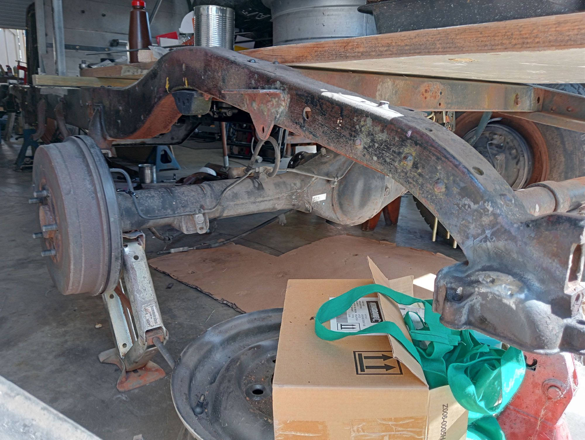
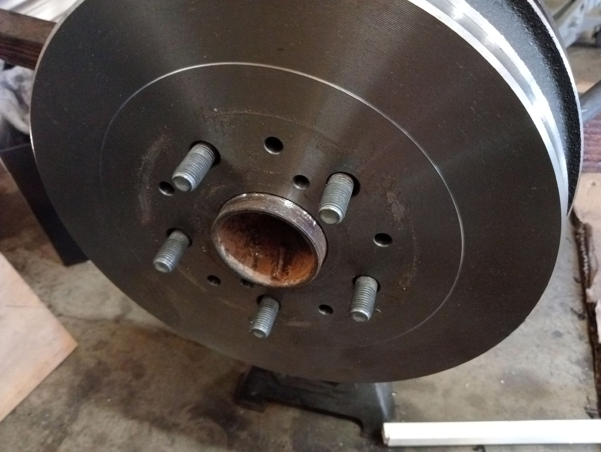
I'm going to be using Ford / Dodge pattern wheels with a 5 x 4.5" PCD so my rear axle choice would ideally be Ford or Dodge , the other requirement is I must have drum brakes with rear wheel handbrake as my R9 overdrive does not have a handbrake drum mounted to it. I have a Fargo 3/4 ton (4.1 ratio) back axle that would be ideal but they don't have handbrakes, not impossible to retrofit but I kept one eye open on marketplace and a 2010 Hilux 2WD 4.1 non ABS rear axle magically appeared.
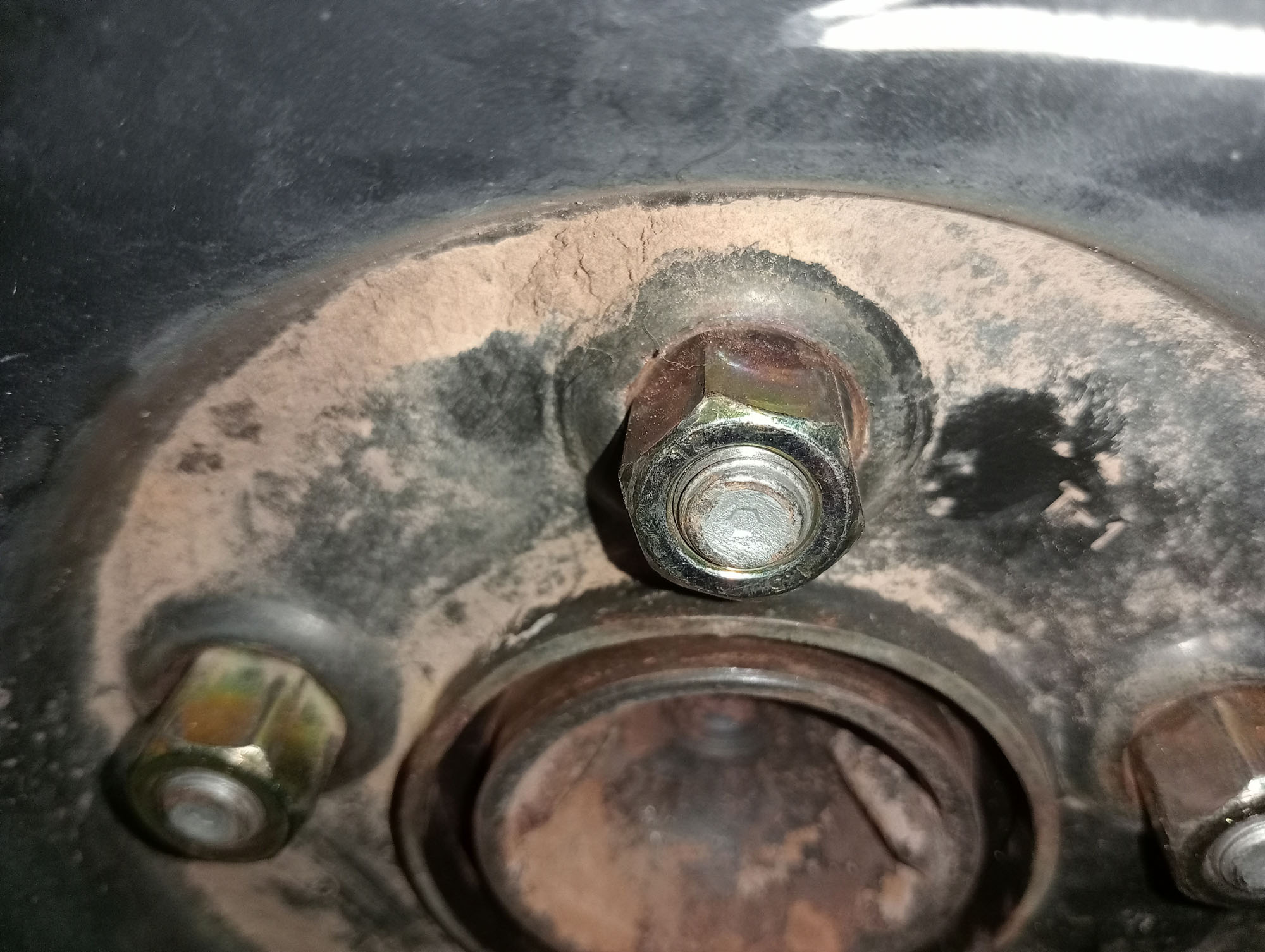
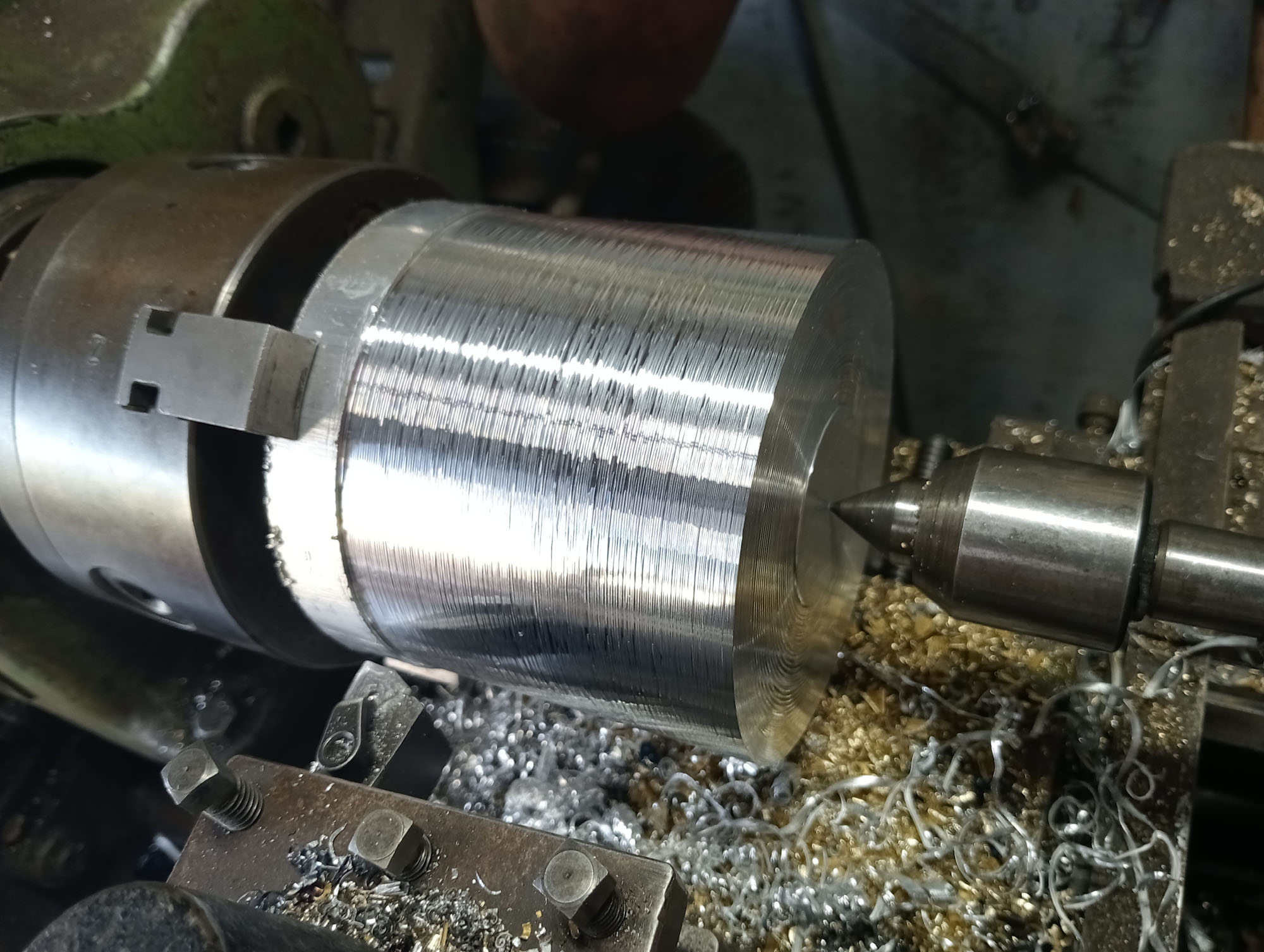
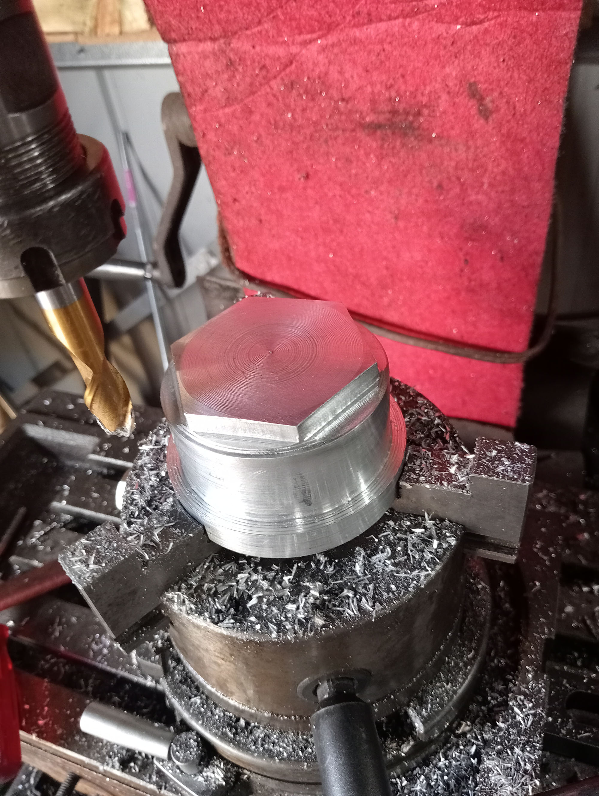
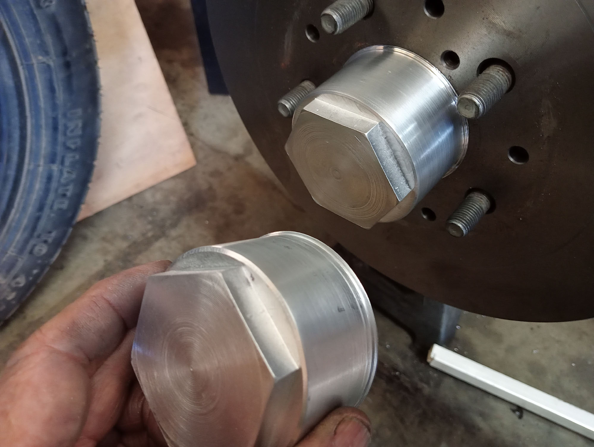
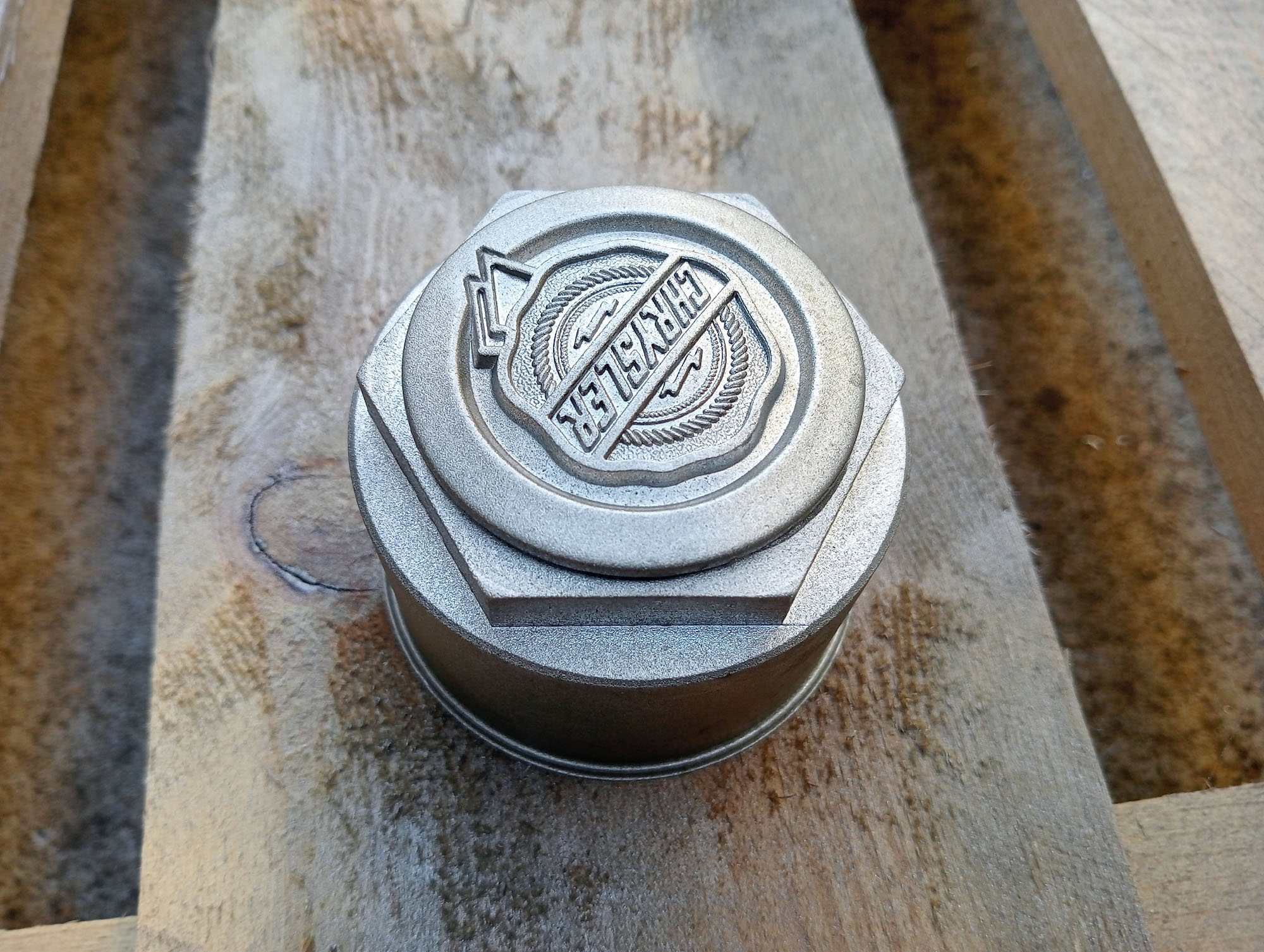
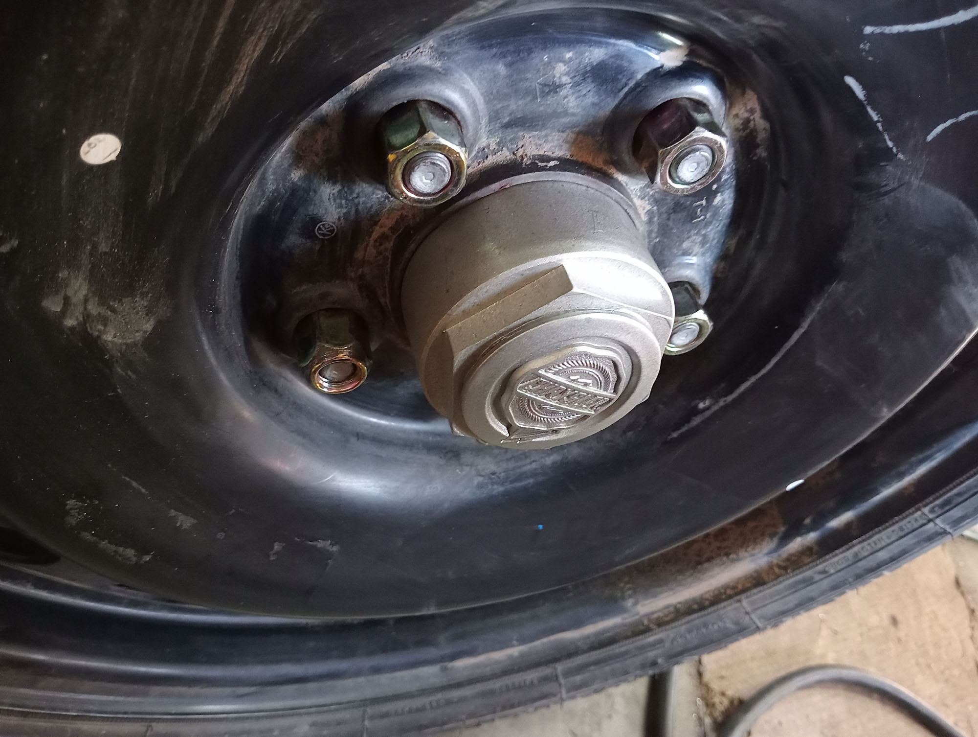
Now you might think a Hilux axle is a most unlikely candidate, but if you know Toyota they were originally copied from 1930's Dodges. and if something works they don't change stuff every year for the sake of it. PCD is still 5 x 4-1/2" so early Dodge wheels fit , but what took me completely by surprise the Spring perches fit EXACTLY over the 1929 Chrysler centre bolts. For all intents & purposes it is a PreWar axle (but with modern seals & metallurgy) . The oinly problem the Chrysler wheel center hole is bigger than the Hilux axle spigot , no drama as the wheels are nut centric, but for extra security I made some hub spigot / center hole adapters which double as a centre cap & look more de rigueur
A 4.1 rear diff with 31" tyres will give
| 2000RPM | 3000RPM | 3600RPM | 4000RPM | |
| 1st 2.43 | 18.5 mph | 27.7mph | 33.3 mph | - |
| 2nd 1.53 | 29.4 mph | 44.1 mph | 52.9 mph | - |
| 3rd 1:1 | 40.9 mph | 61.35 mph | 73.6 mph | - |
| OD .722 | 62.31 mph | 93.46 mph | 112.16 mph | 125 mph |
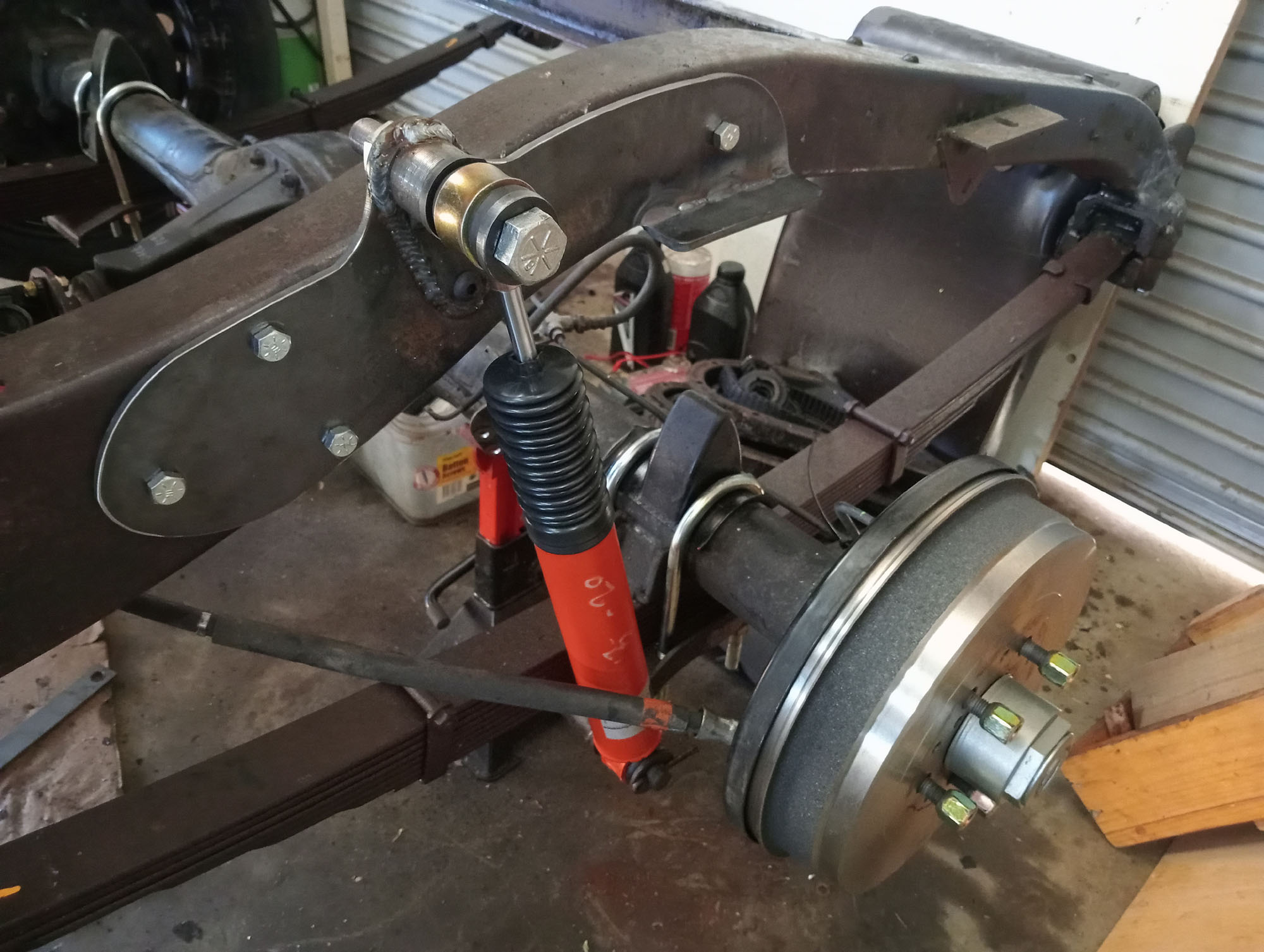
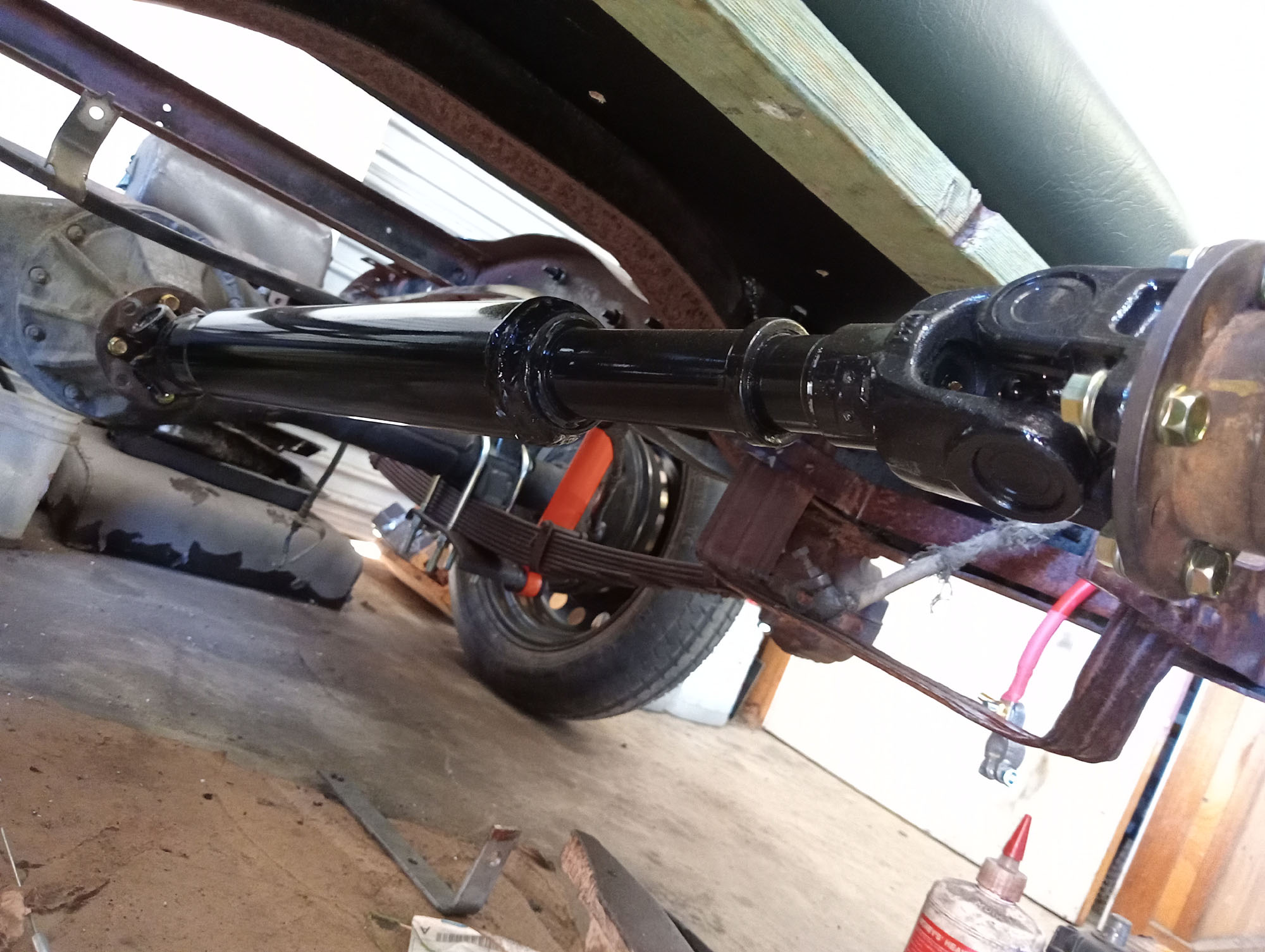
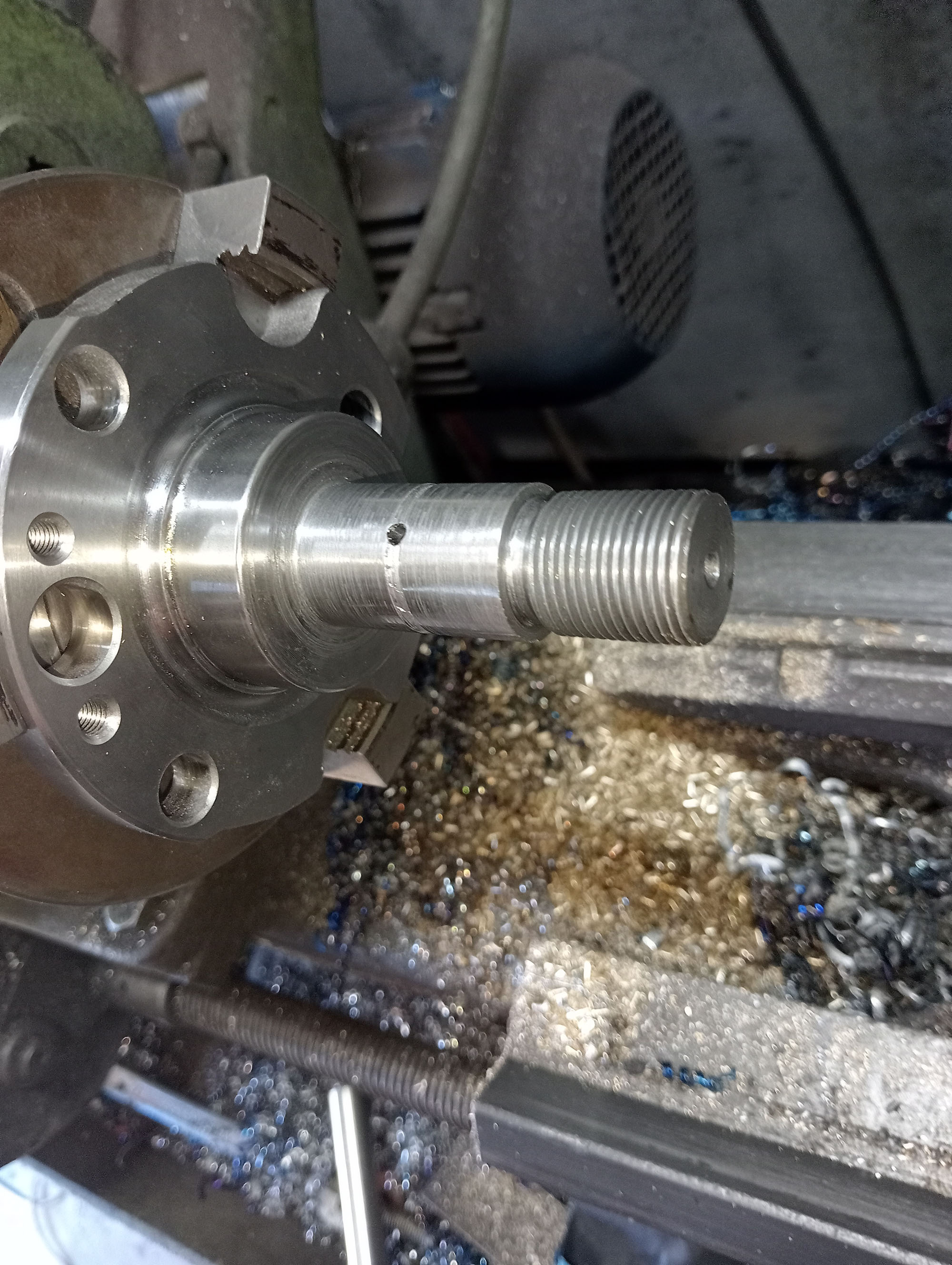
The tailshaft is a shortened Hilux 4x4 LN167 rear shaft, Shorten & balance by Super Balance in Shepparton. The spigot on the Packard output flange needed slight adjustment on the lathe & the Hilux yoke bolted right on.
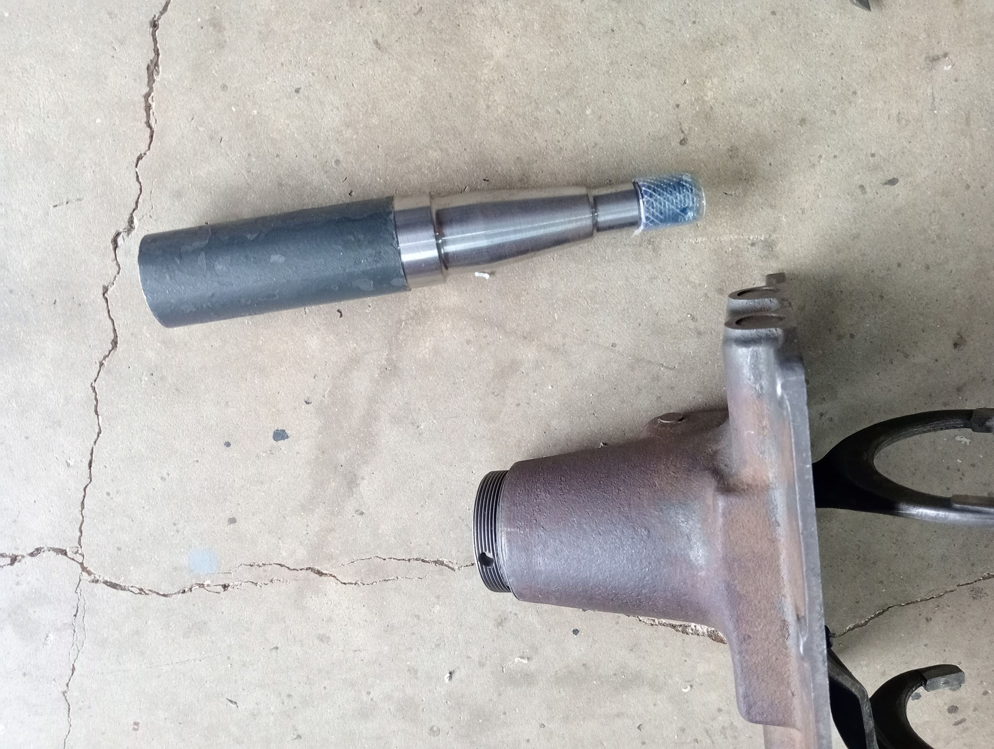
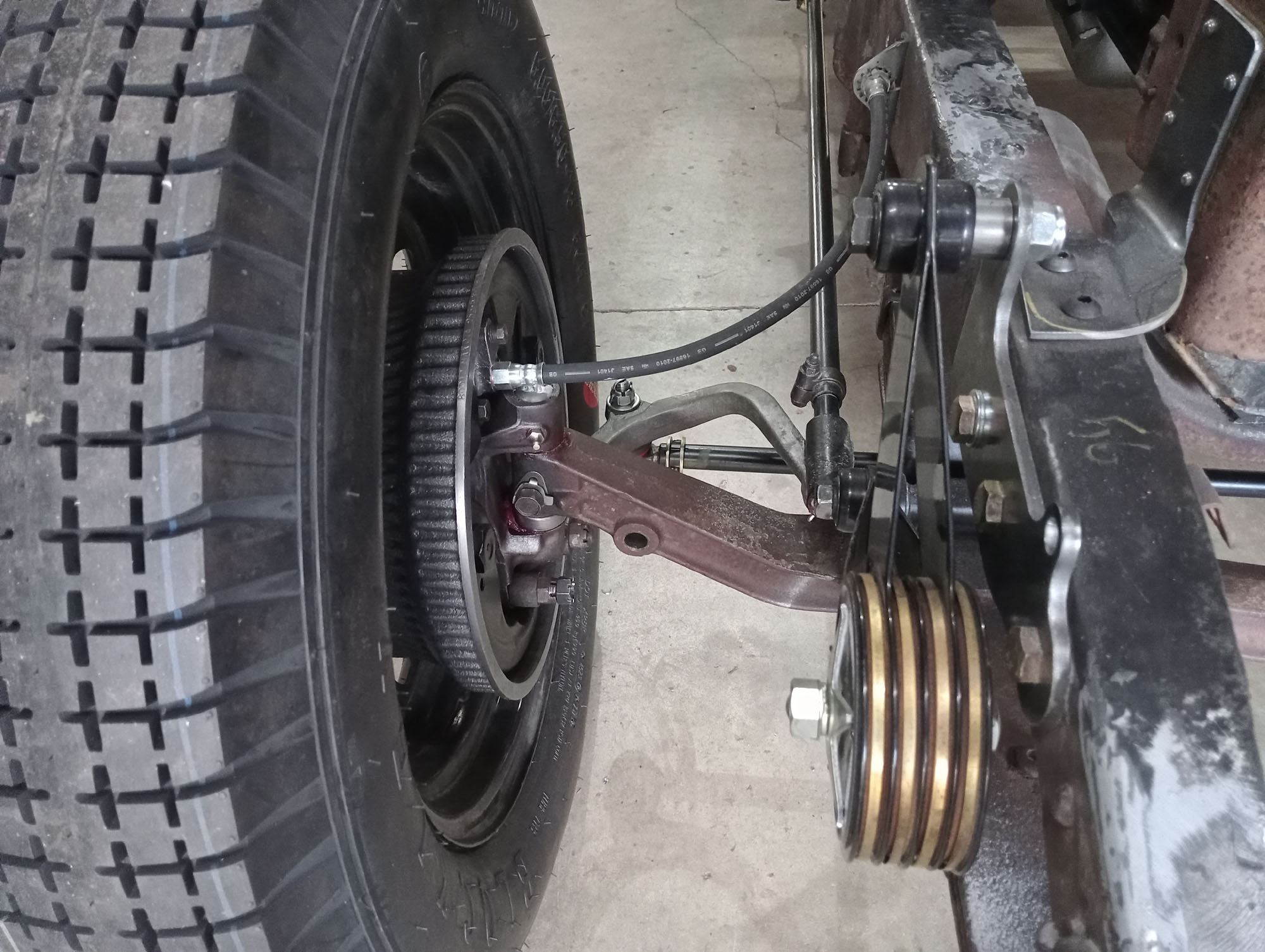
Front Axle
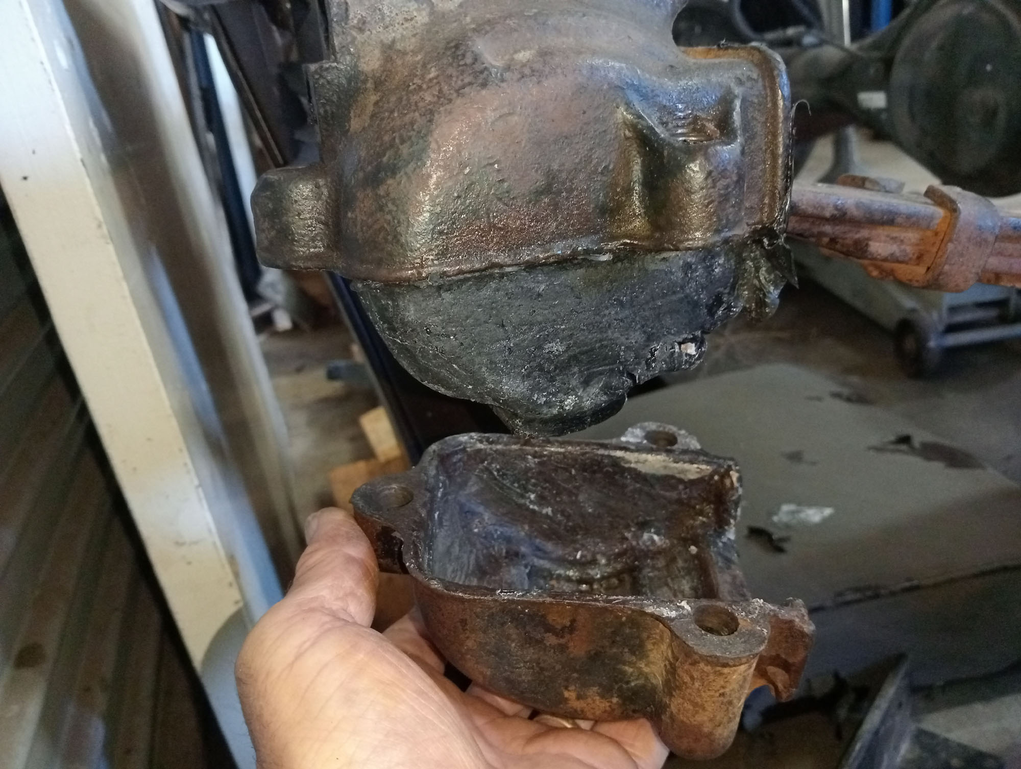
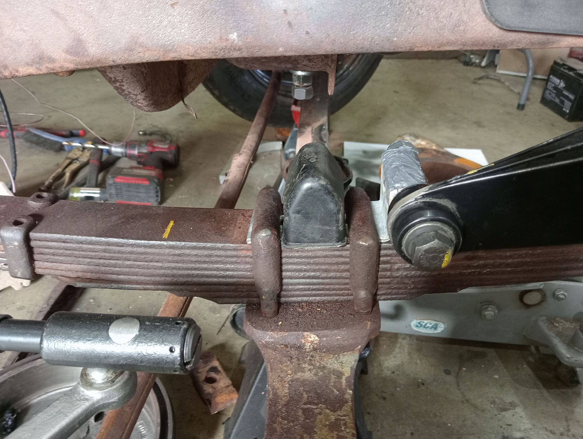
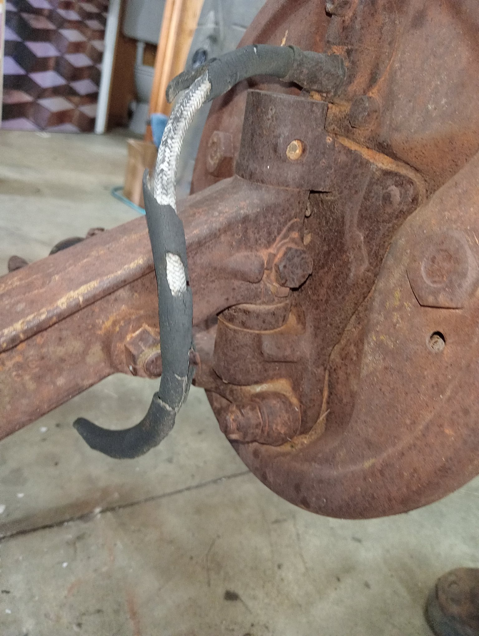
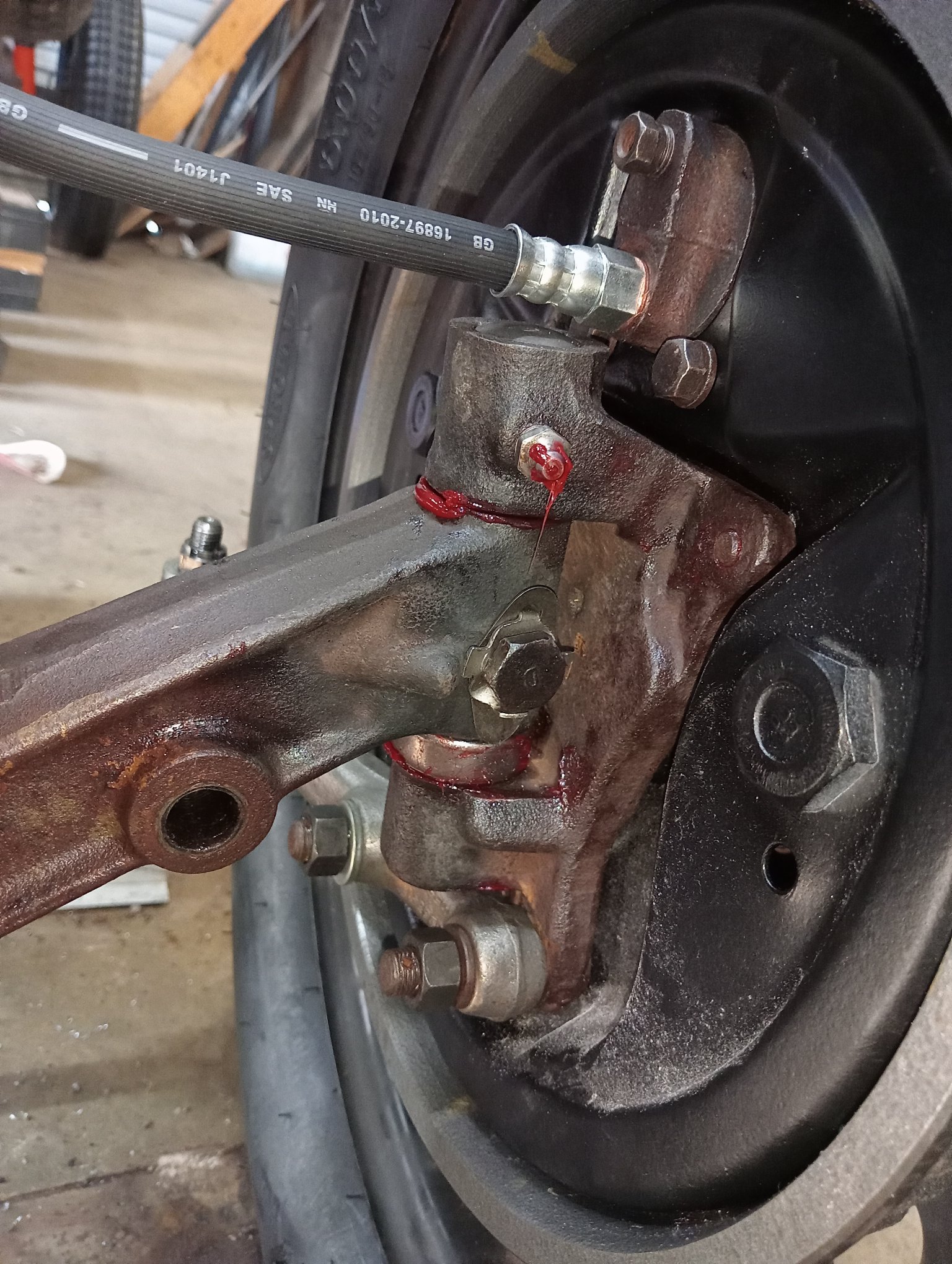
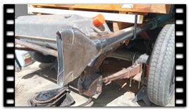
The front axle for a 1927 Chrysler 75 Series is a Tubular axle with 14" brakes, these are hard to find and would have been a sought after item on a pre ASRF Hot Rod. I did find one on a farm wreck in Yackandandah but its broken, potentially repairable or could be re-tubed . Instead I farm picked a late 1930's 3/4ton Fargo chassis with a good I-Beam axle. The Fargo axle has more drop than the original axle so will suit this build better. Being in the Chrysler family its no surprise that the Spring perches on the axle fit perfectly over the front spring centre bolts on my 1929 Chassis..
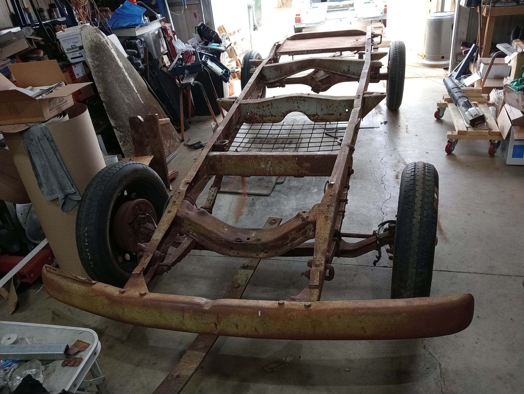
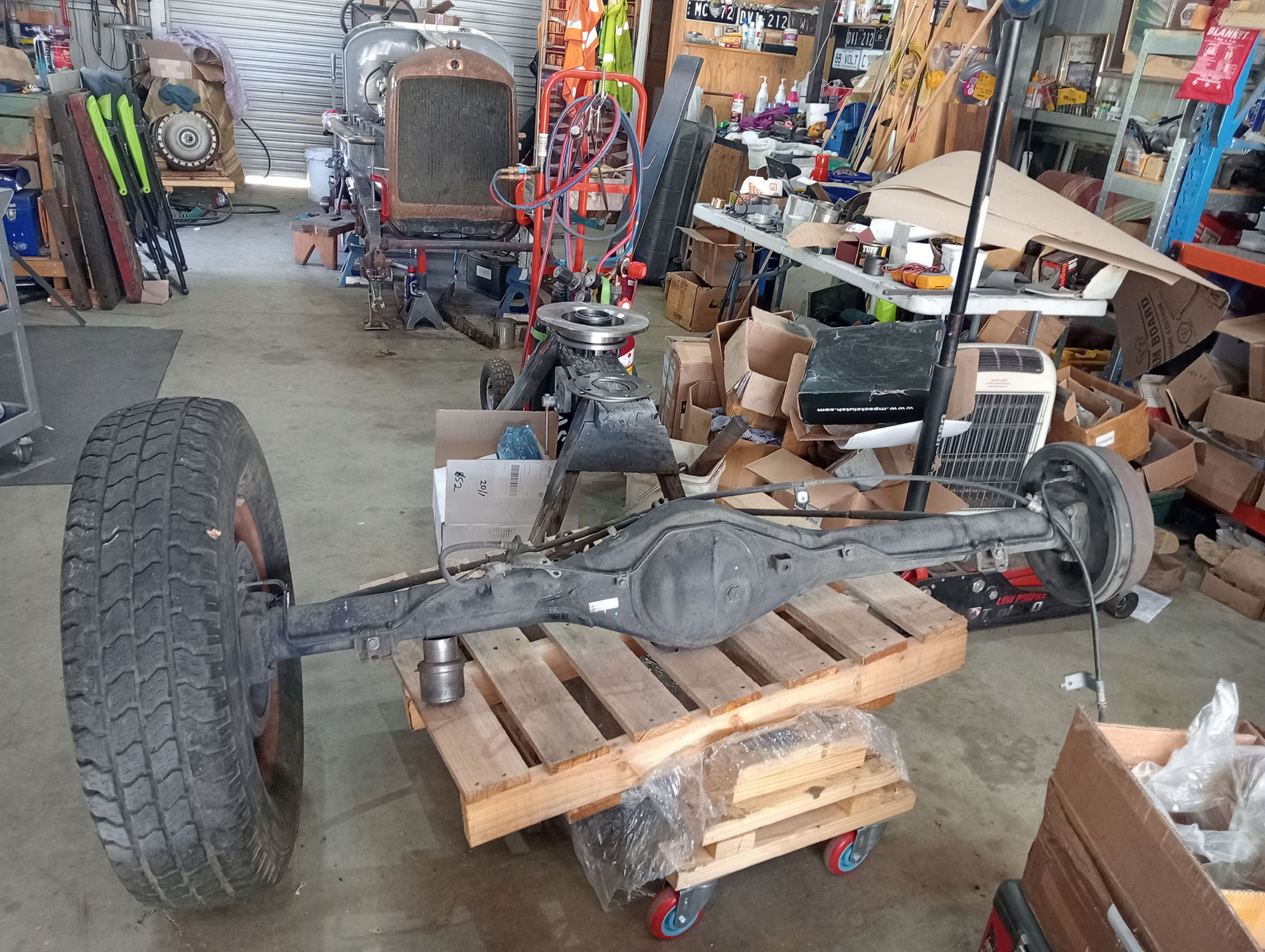
The photo on the left is the Fargo chassis picked fresh from a local farm, The right hand chassis rail has a long crack so not much good but the Front axle is very good , save for stuffed tie rod ends and sloppy king pins.
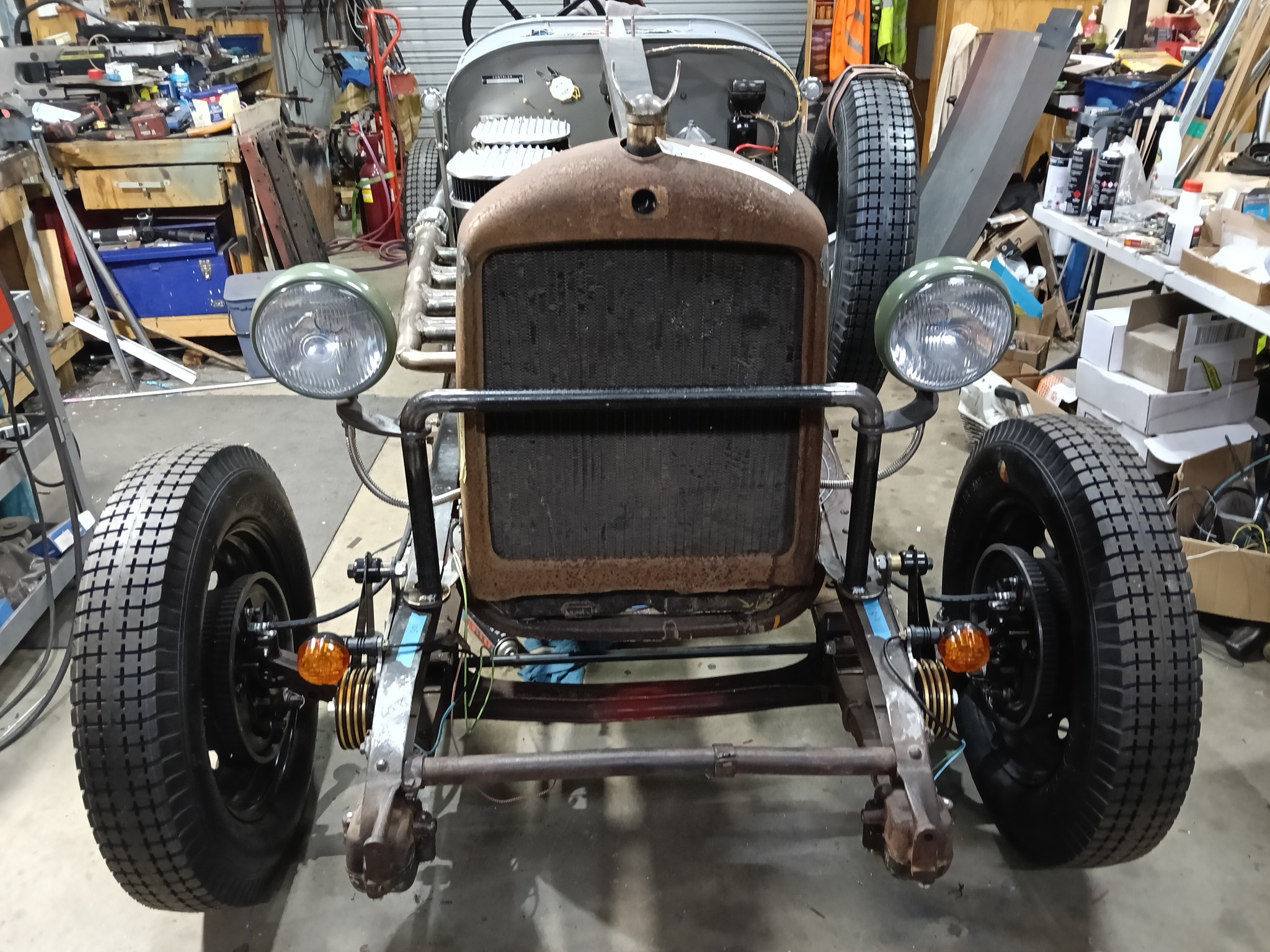
Second photo shows the Fargo axle bolted to the Speedster, Milestone photo from 30 March '25 showing the car sitting on 4 wheels for the first time.
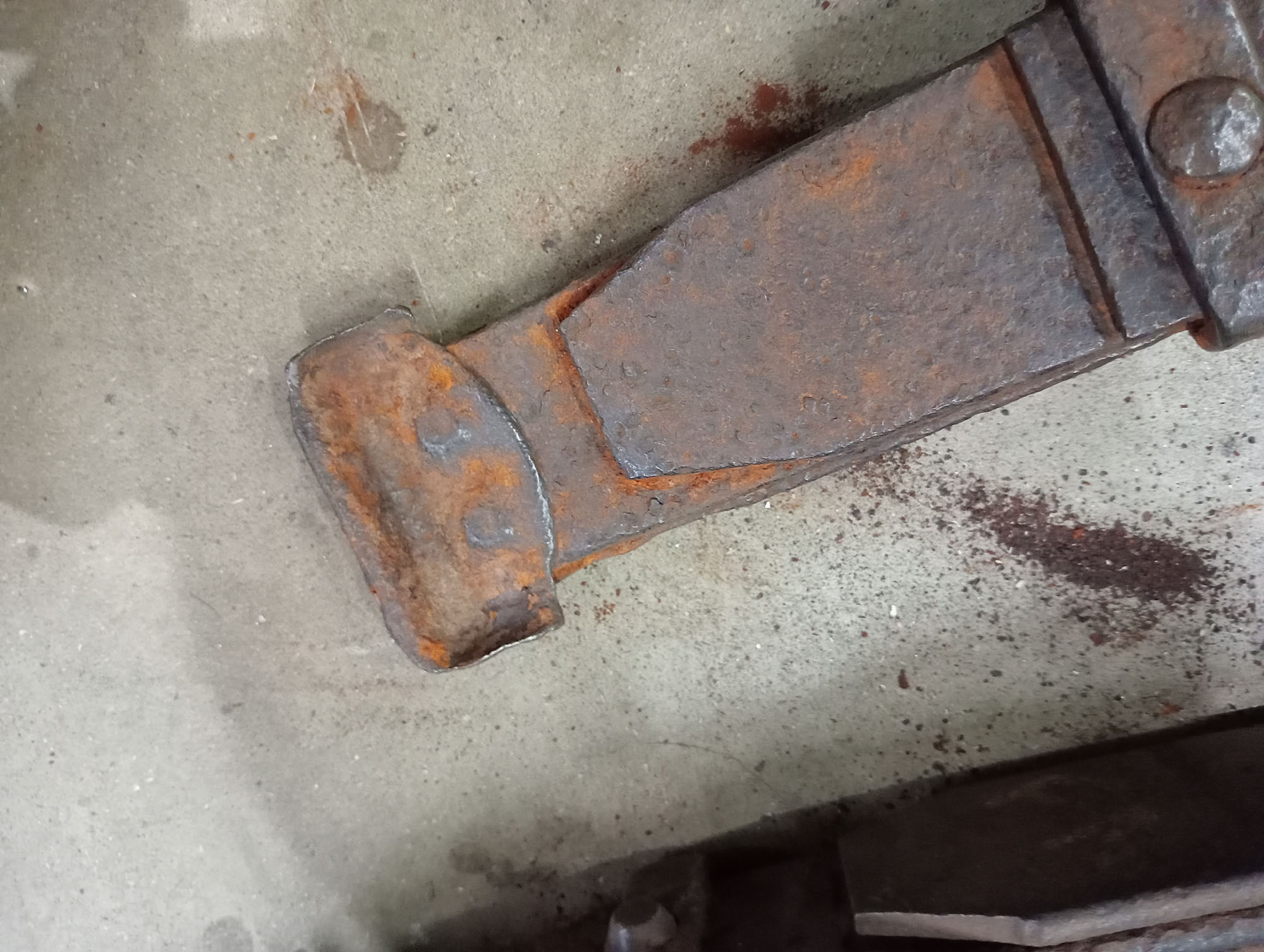
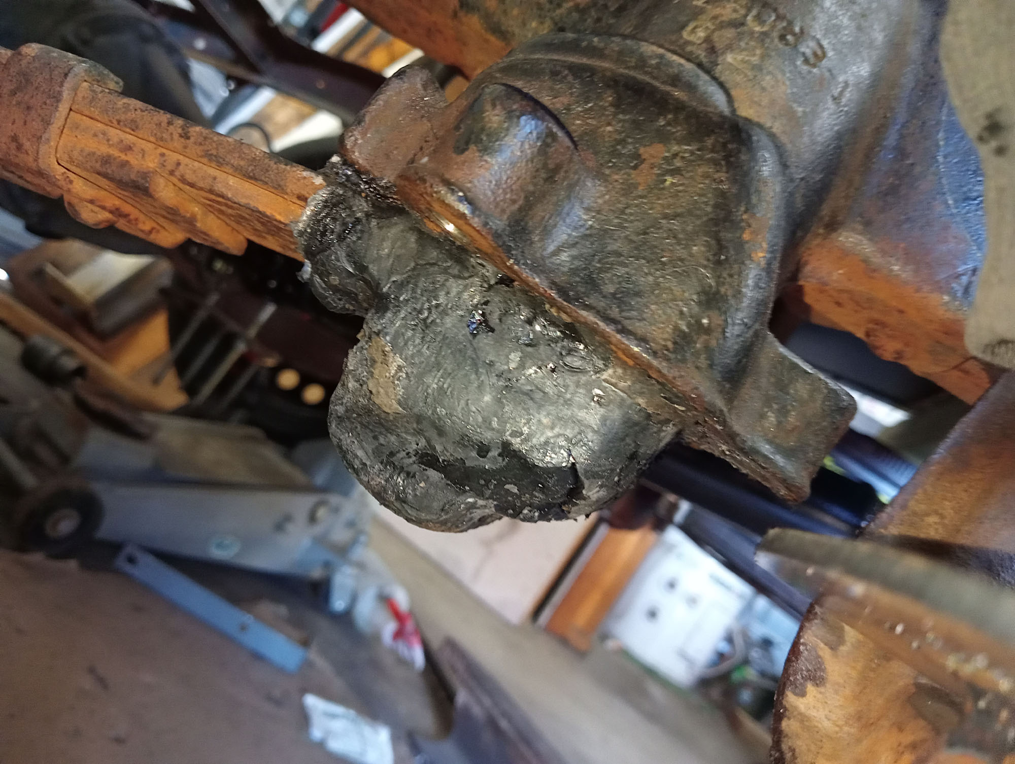
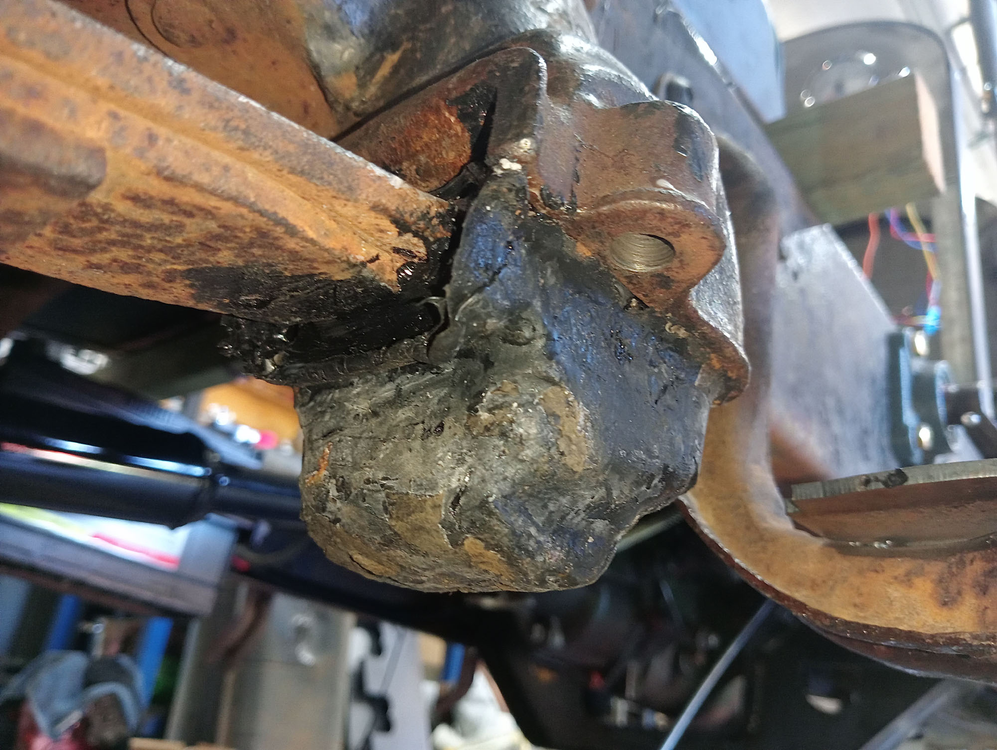
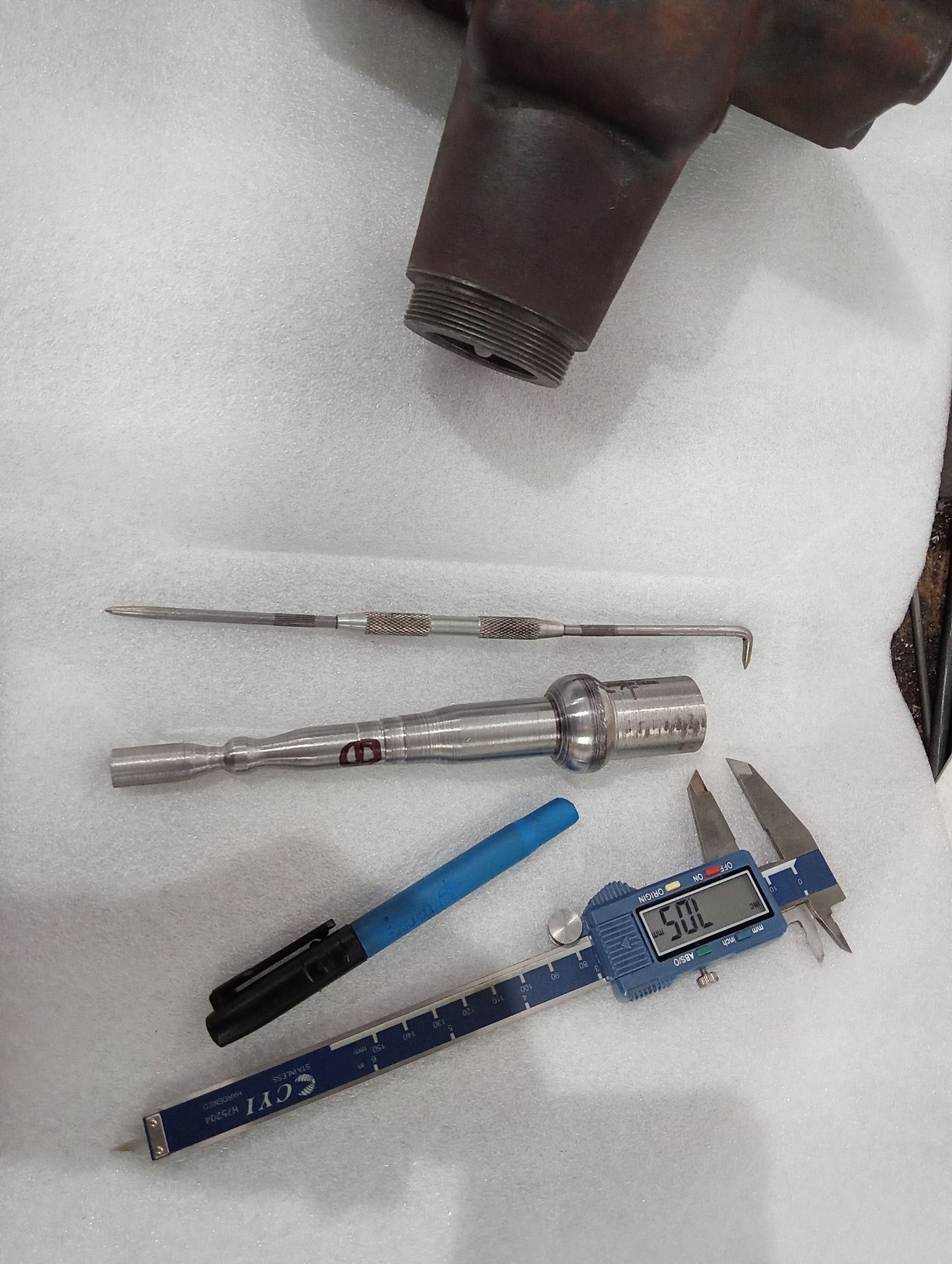
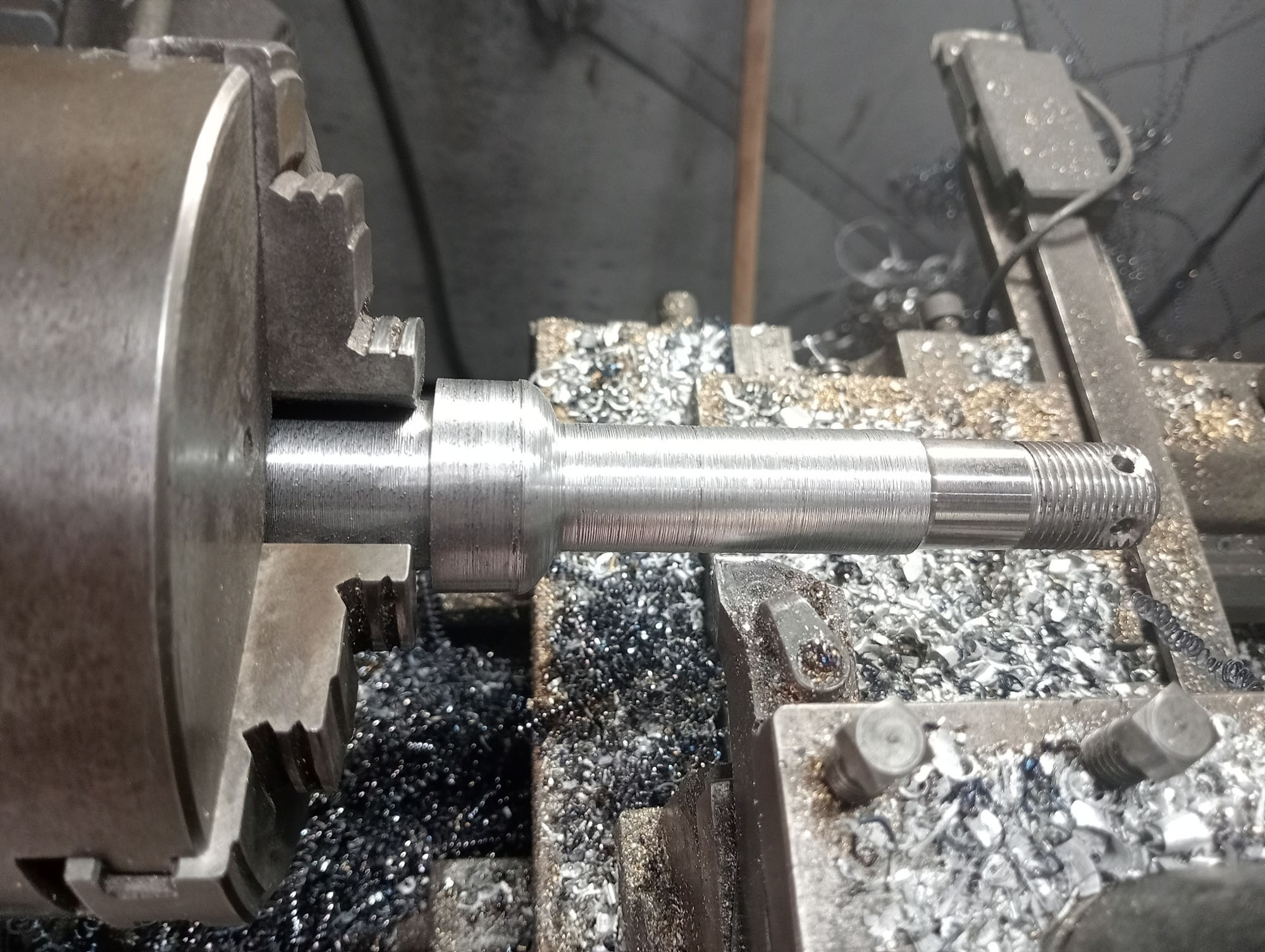
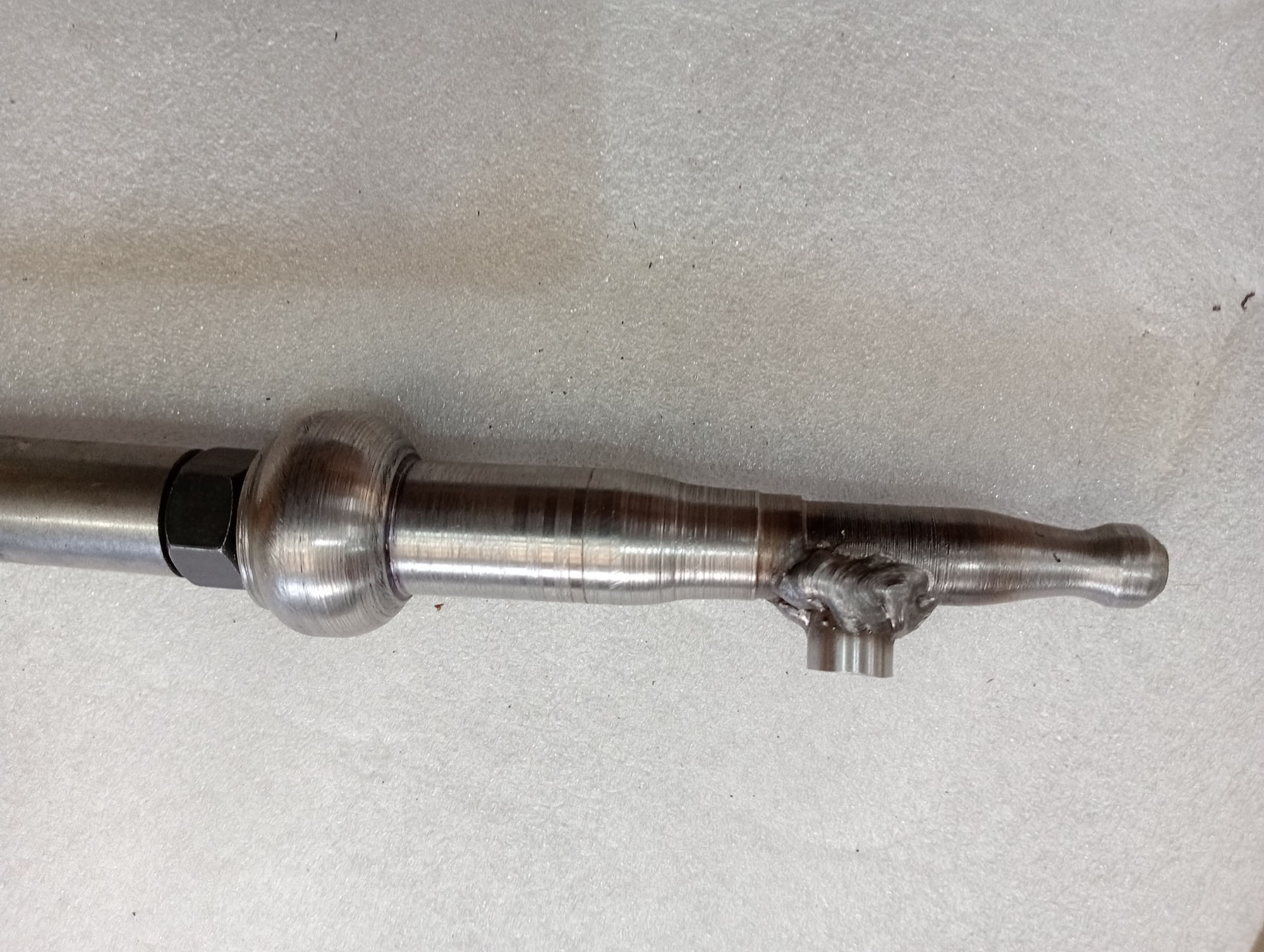
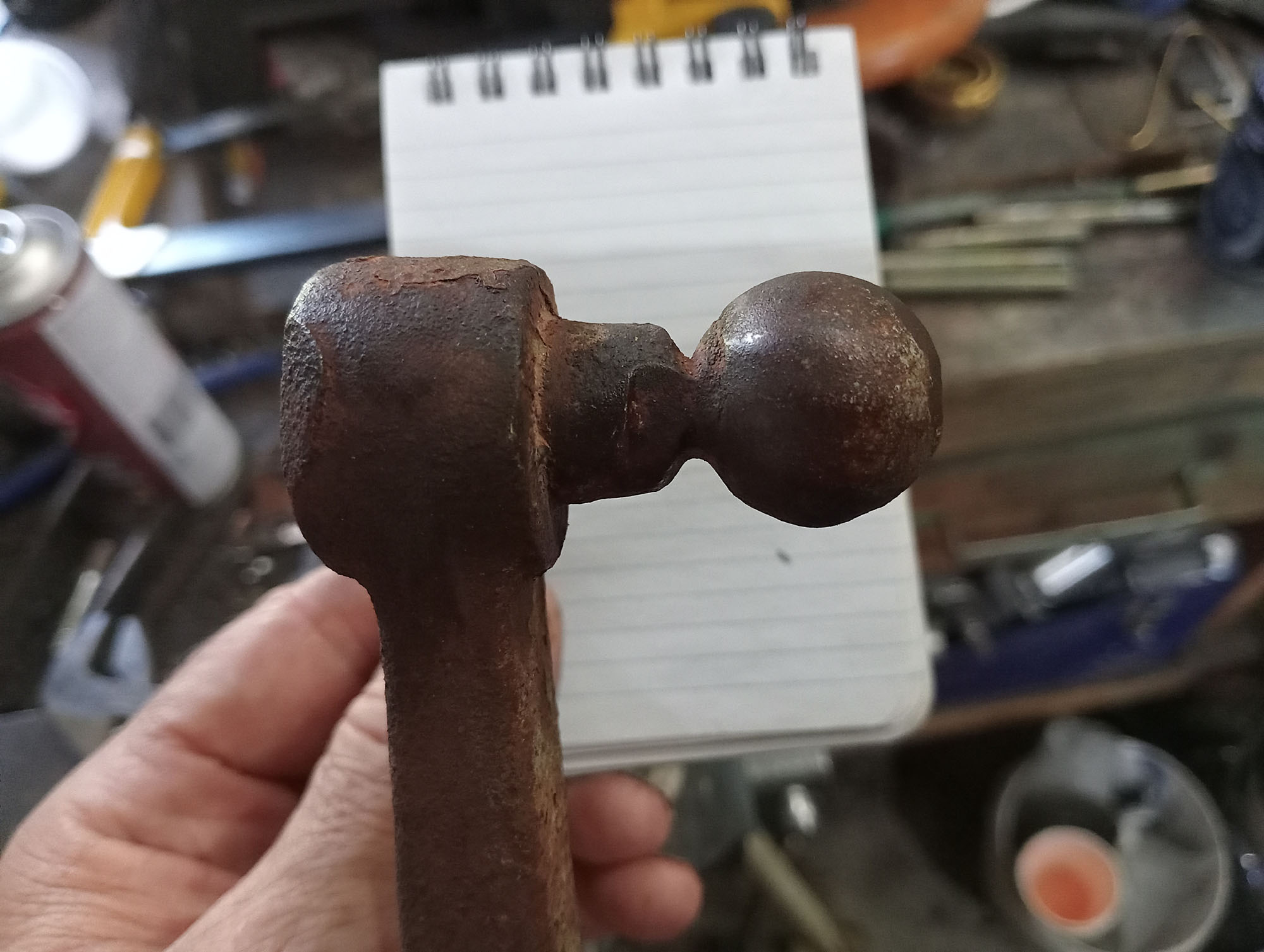
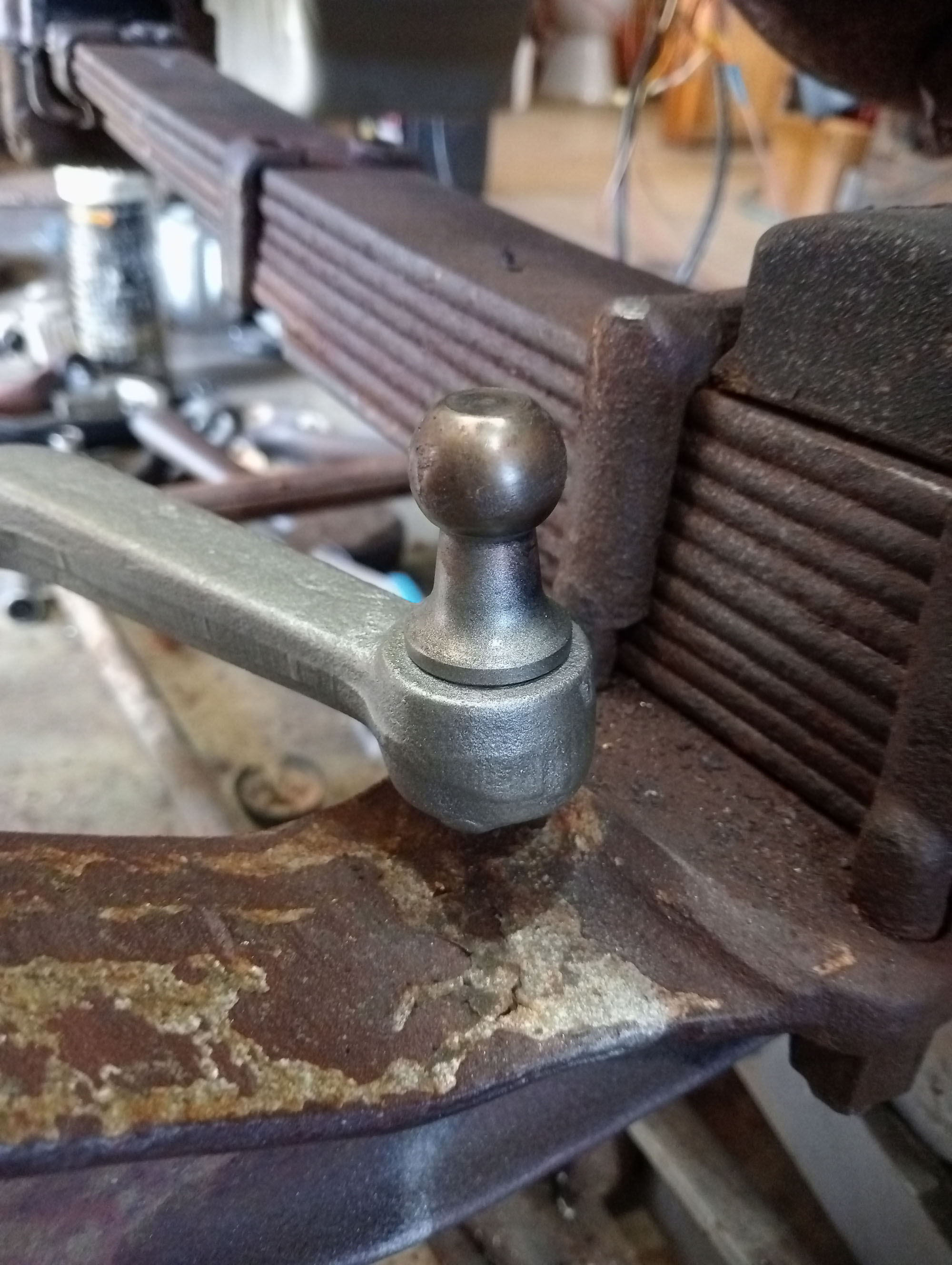
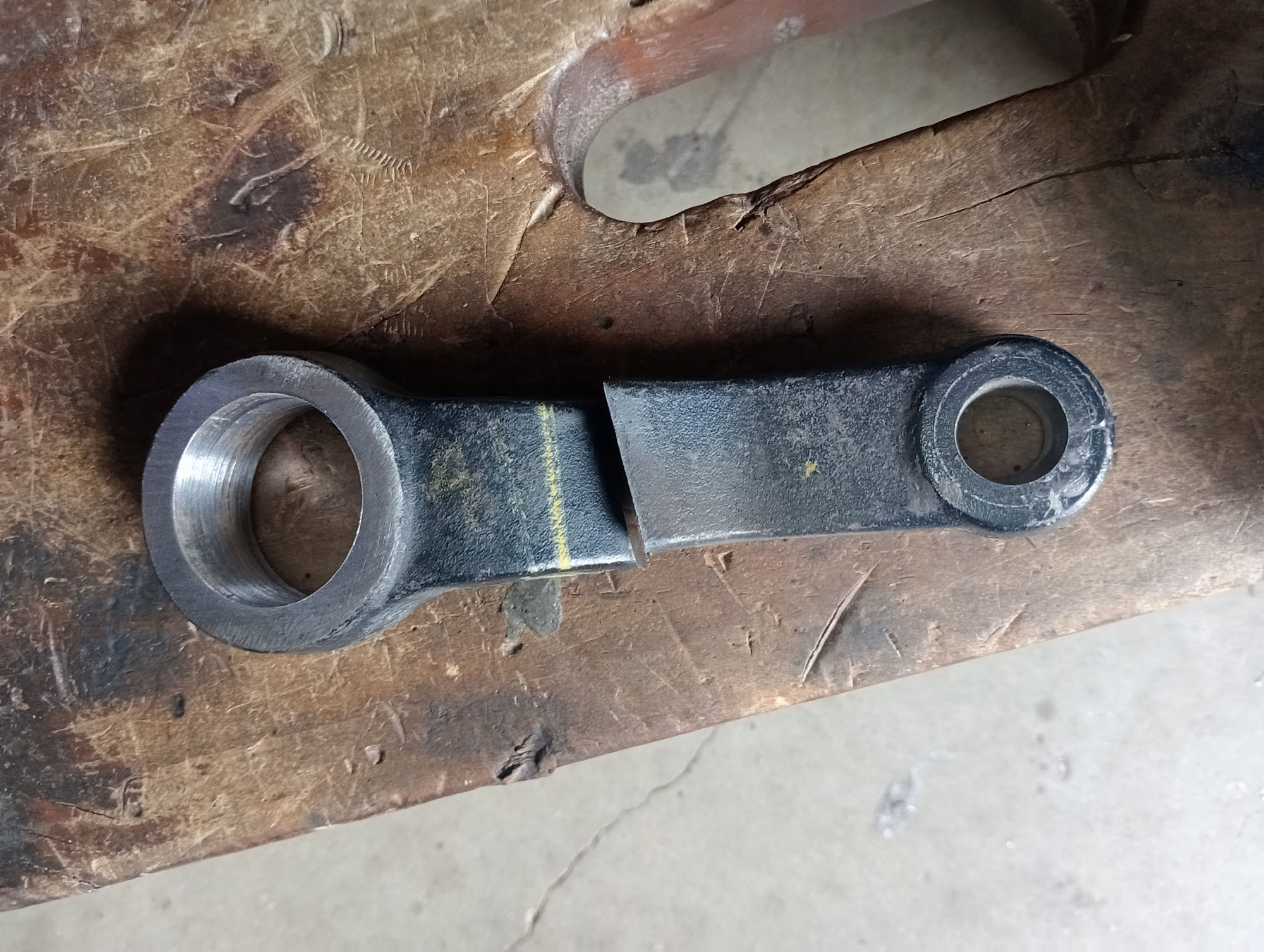
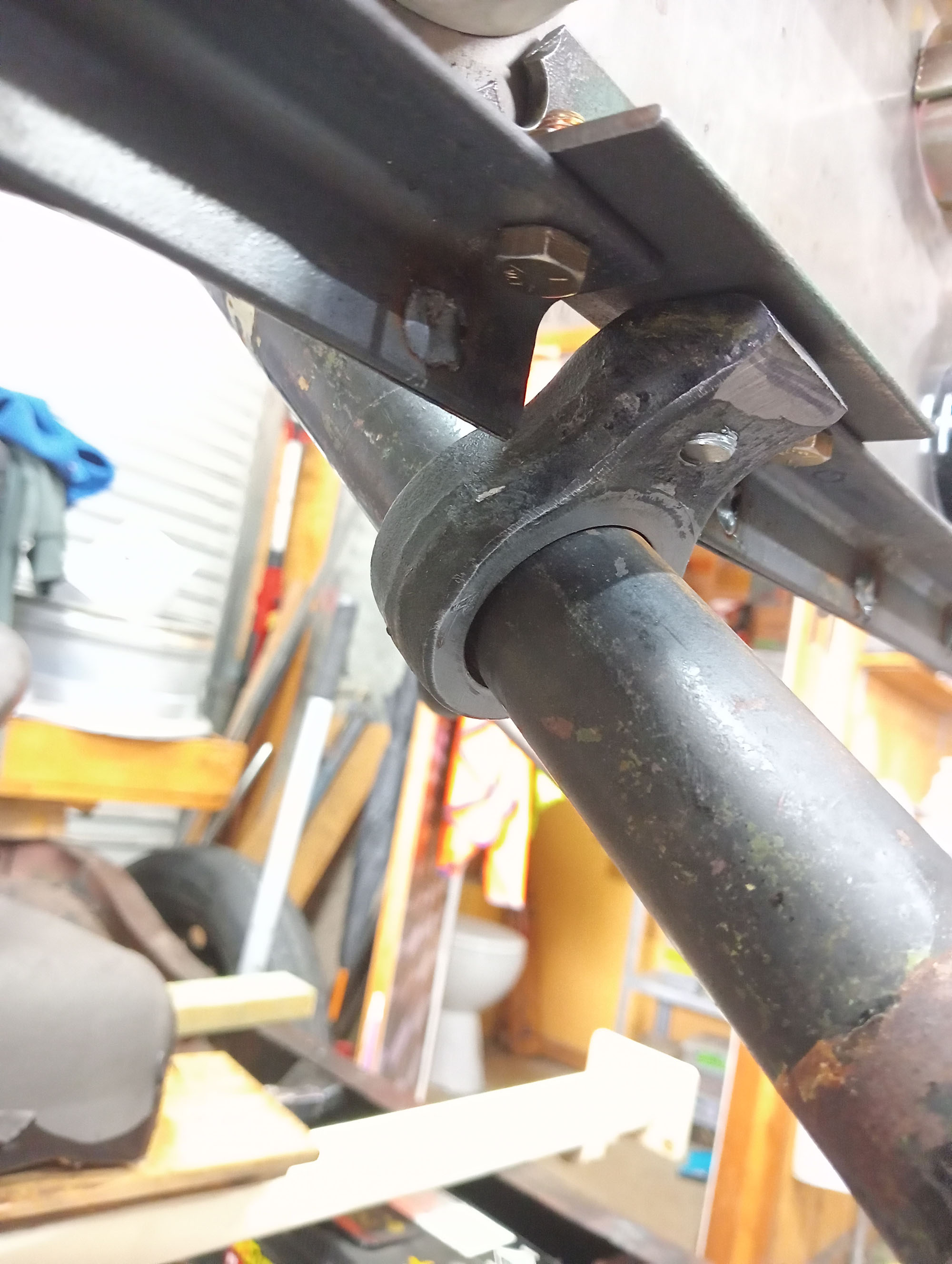
The photos to the right show the original drag link ball end hanging on for its life, there is not much metal there . The replacement ball knuckle is from a Live axle 4x4 Toyota Hilux (1979-1999) and is an identical interchange for Dodge trucks from mid 1930's through to mid 1960's
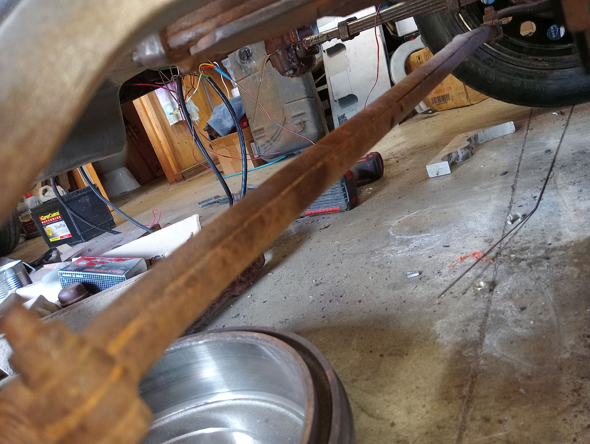
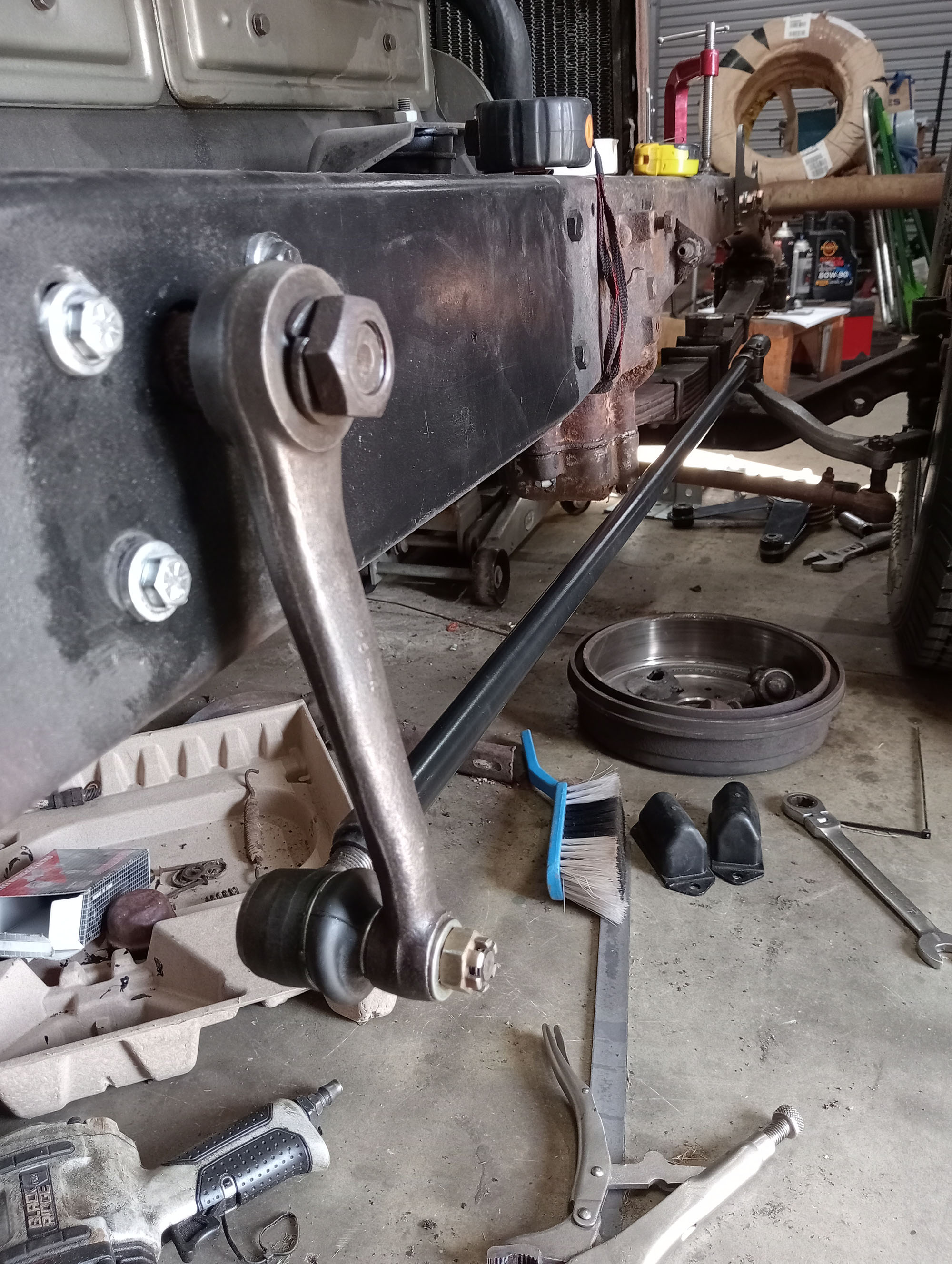
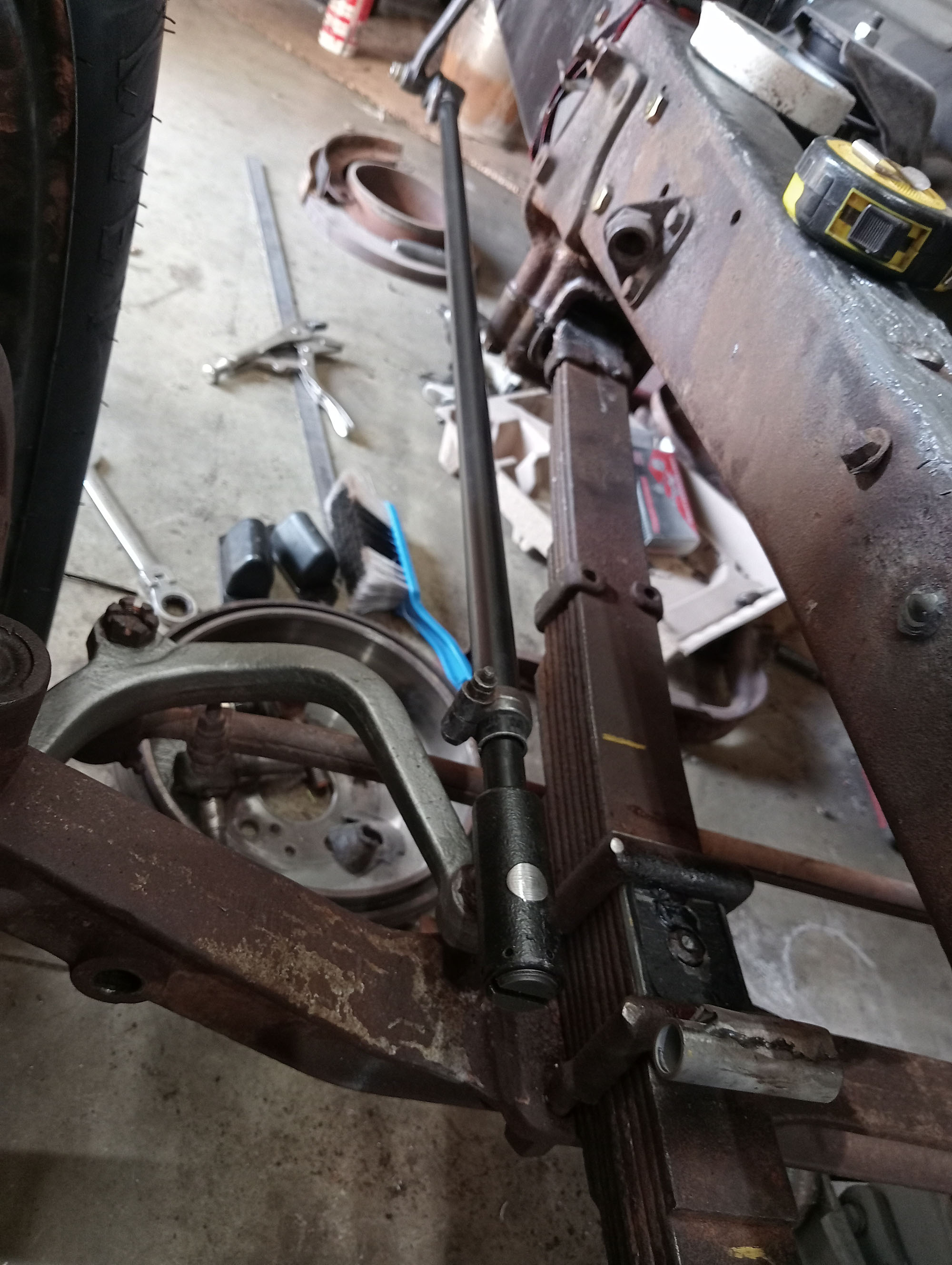
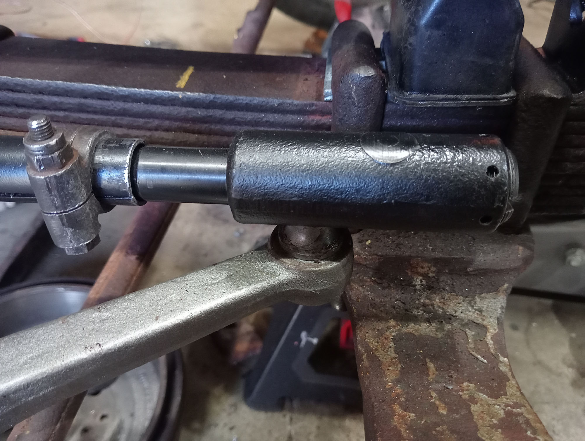
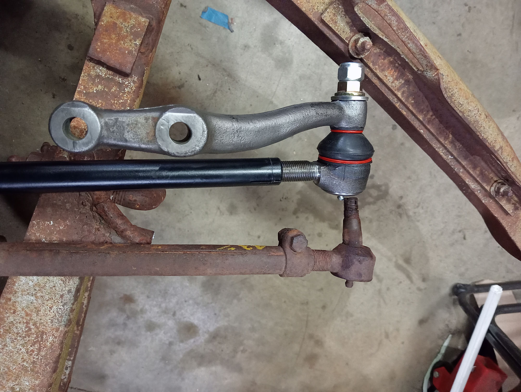
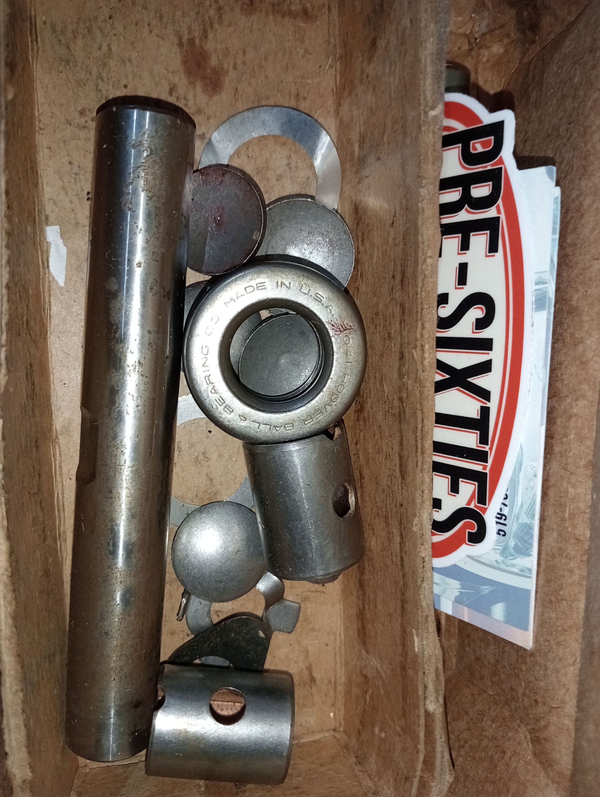
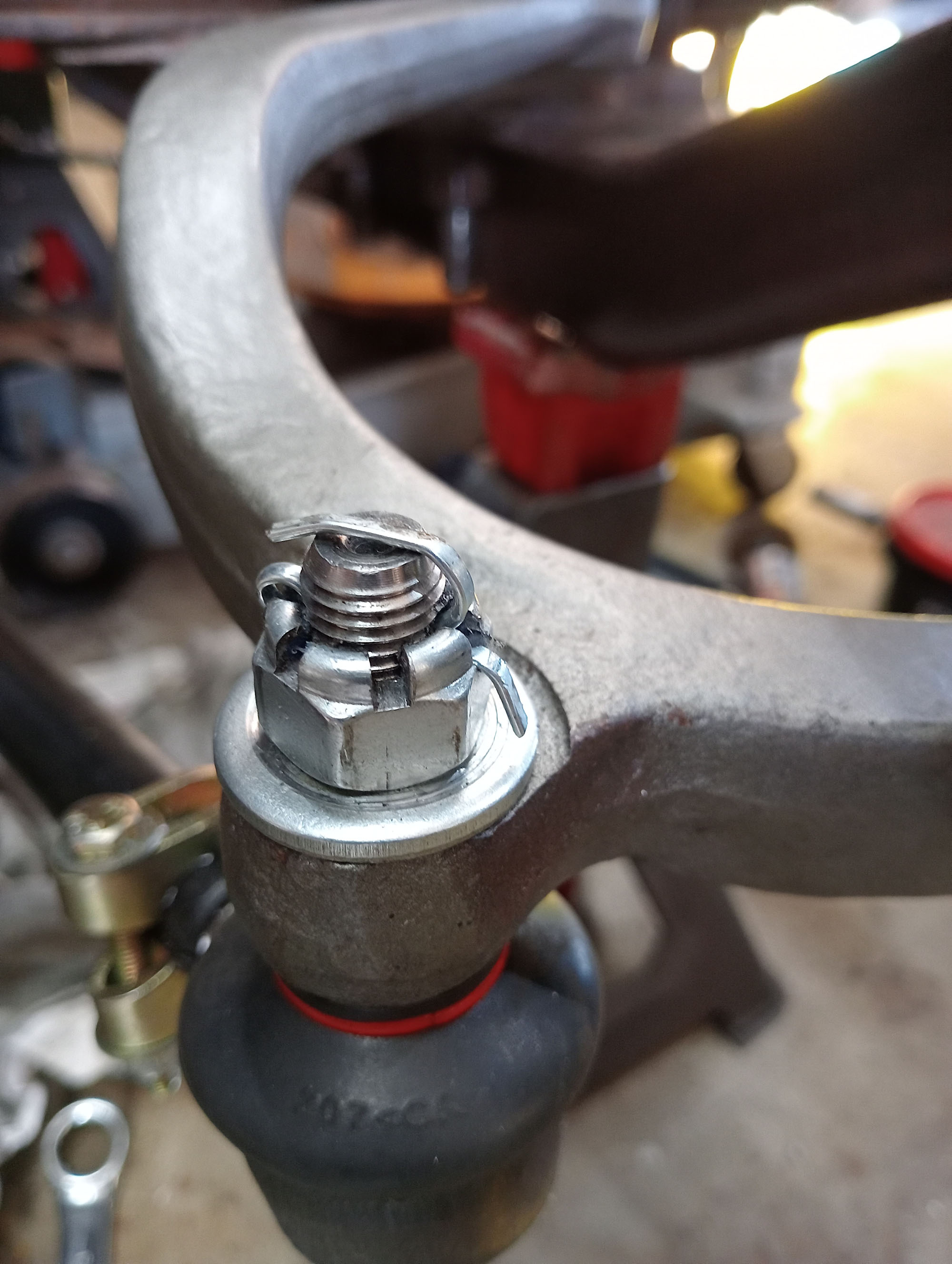
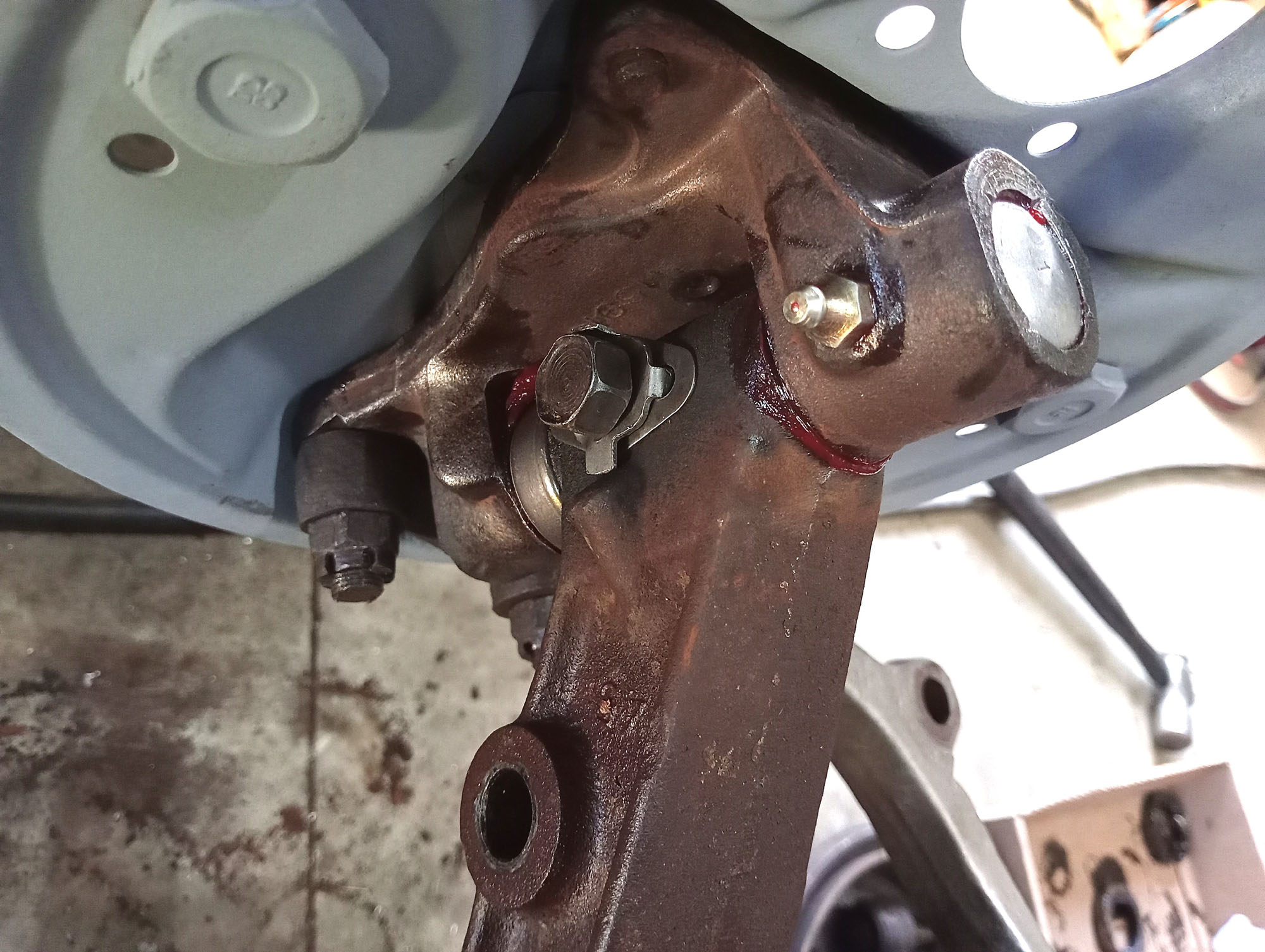
New OE king Pin kits are from Canada, The old rack Rod was beyond help, I replaced with a new Land Rover Series3 track rod & tie rod ends , Drag Link is another new Land Rover track Rod , shortened & re-threaded to suit the Hilux ball link end.
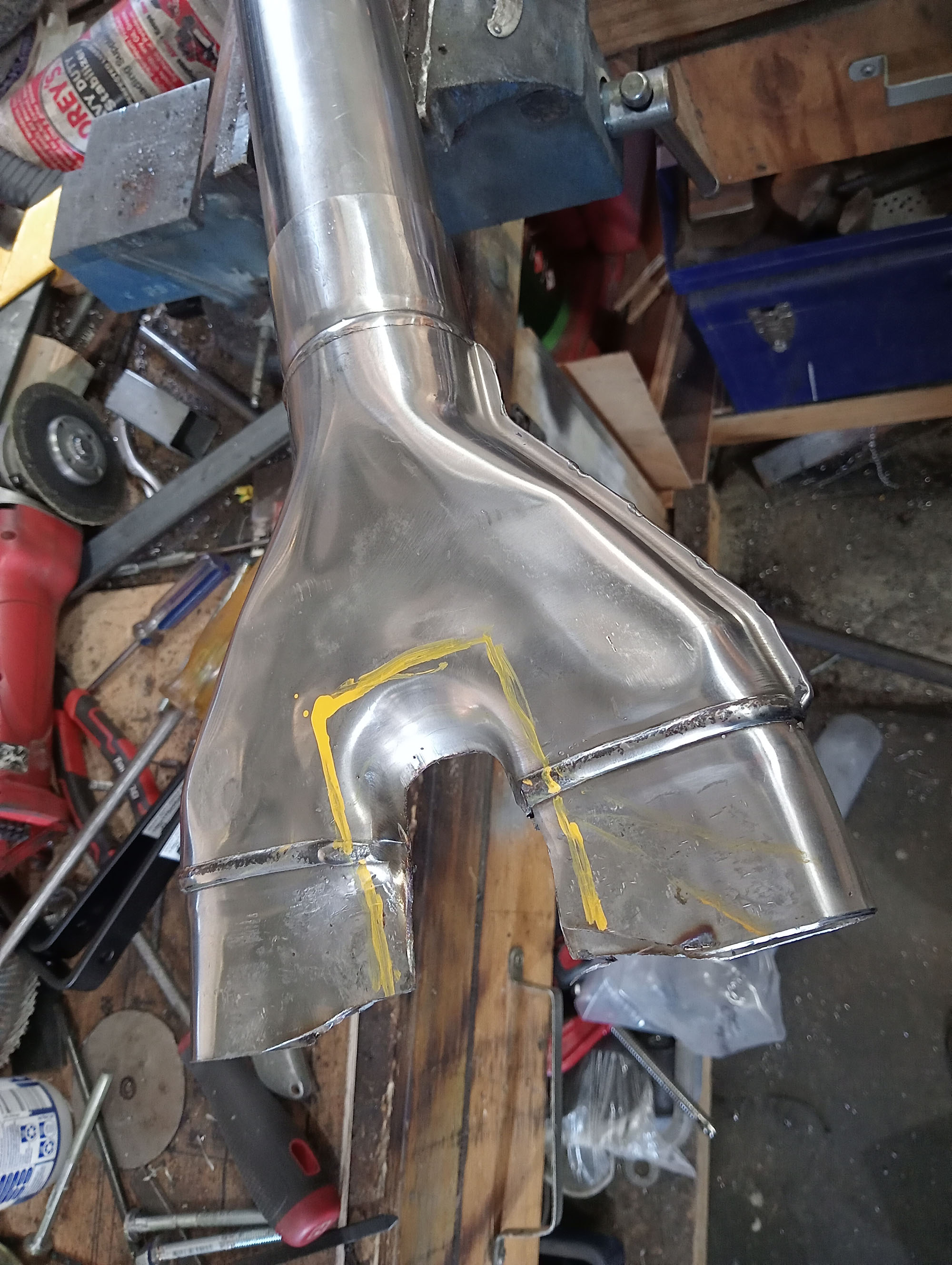
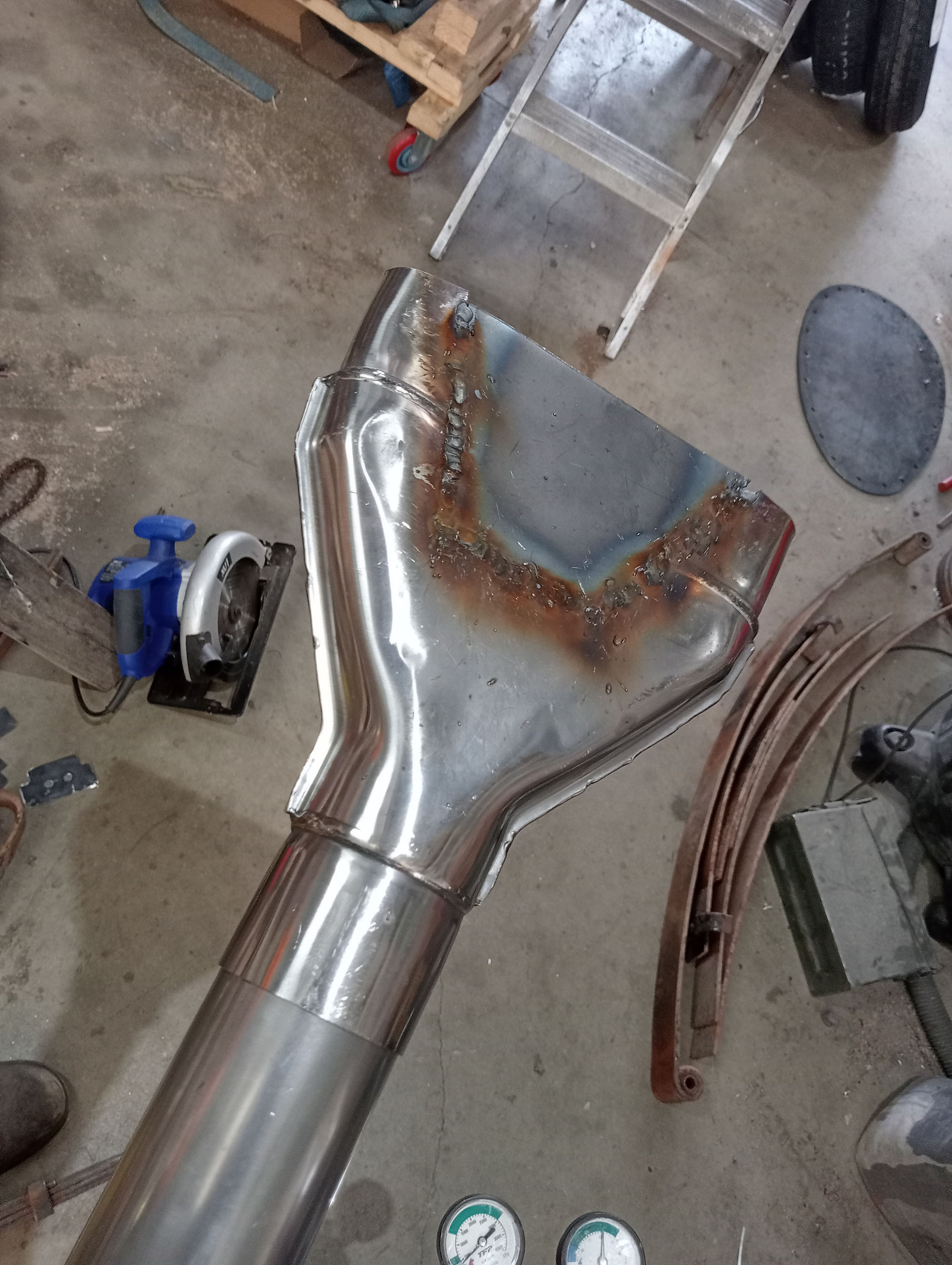
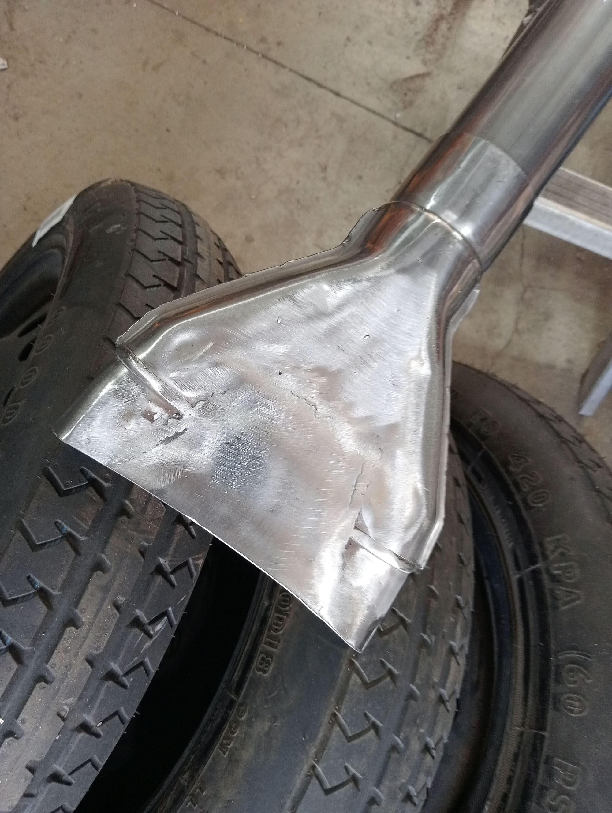
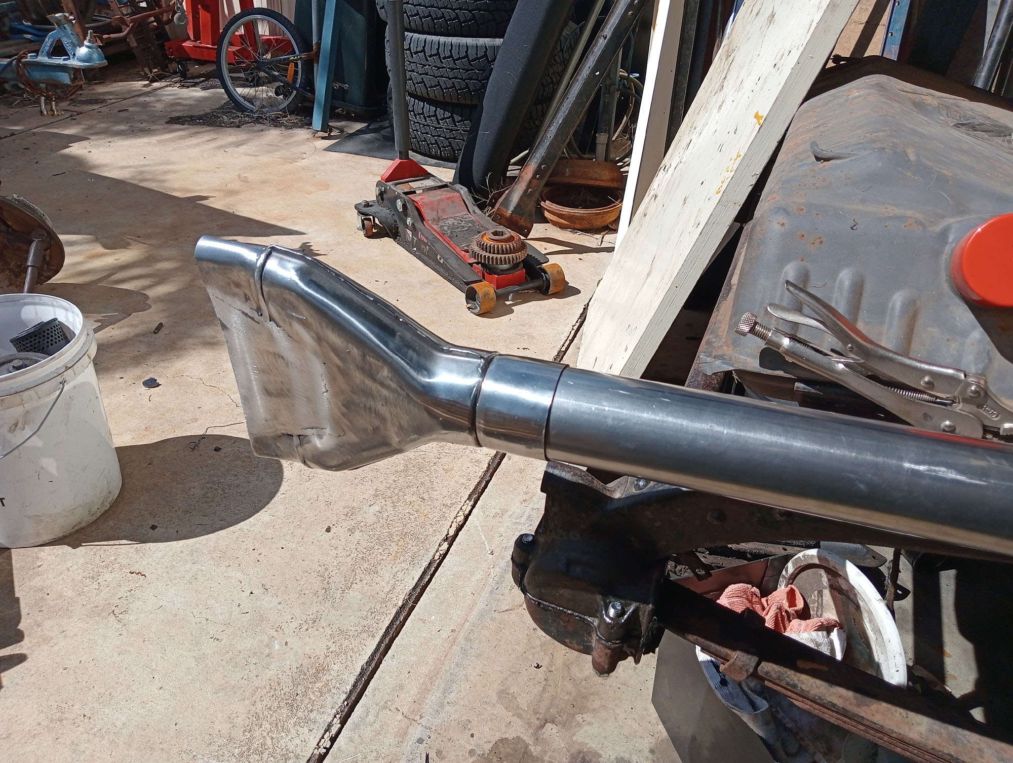
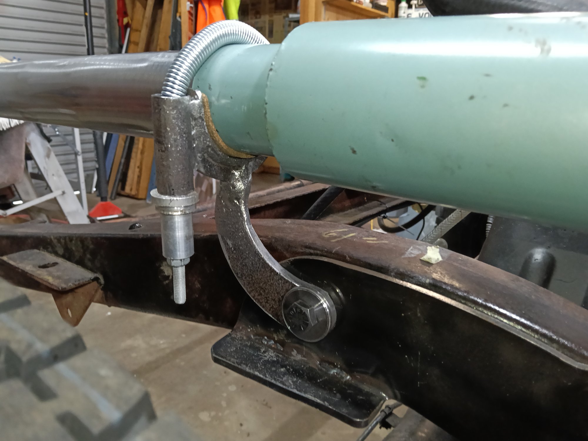
Exhaust & Fishtail tip
The Exhaust is mild steel 2-1/2" with a Vintage Smithys muffler. Fishtail tips were used on cars of this style the 1930's and went out of fashion but are still popular on Harley Davidson motorcycles for some reason. I made this one from a 2 into 1 exhaust Y adapter.
The exhaust is supported in a saddle with a spring over the top.
Brakes
I usually convert everything to disc brakes, They are easier, cheaper, more reliable, just better than drum brakes in every way. But I'm building this car to VSI-33 so it has to be drum brakes. Disc brakes require engineering inspection & the build would then be under ASRF guidelines & become a Street Rod rather than a Pre-War Replica.
So drum brakes it is.
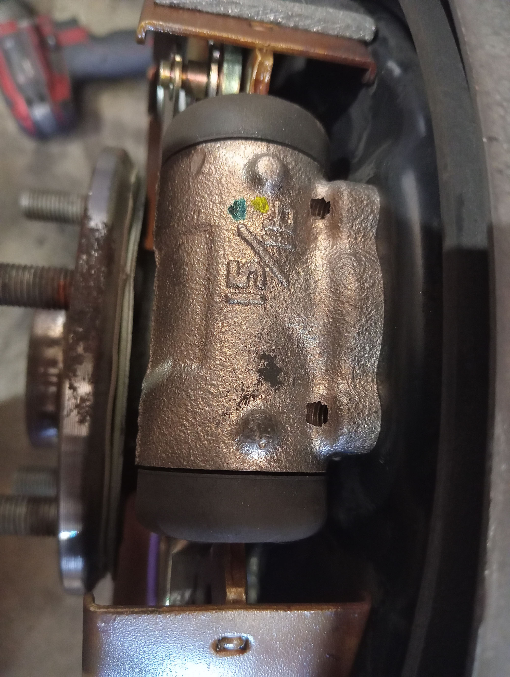
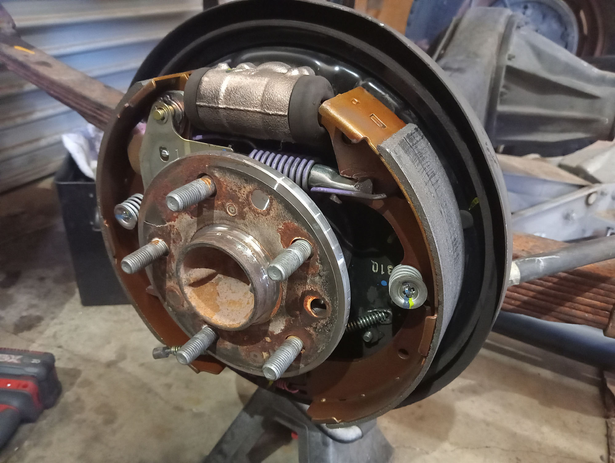
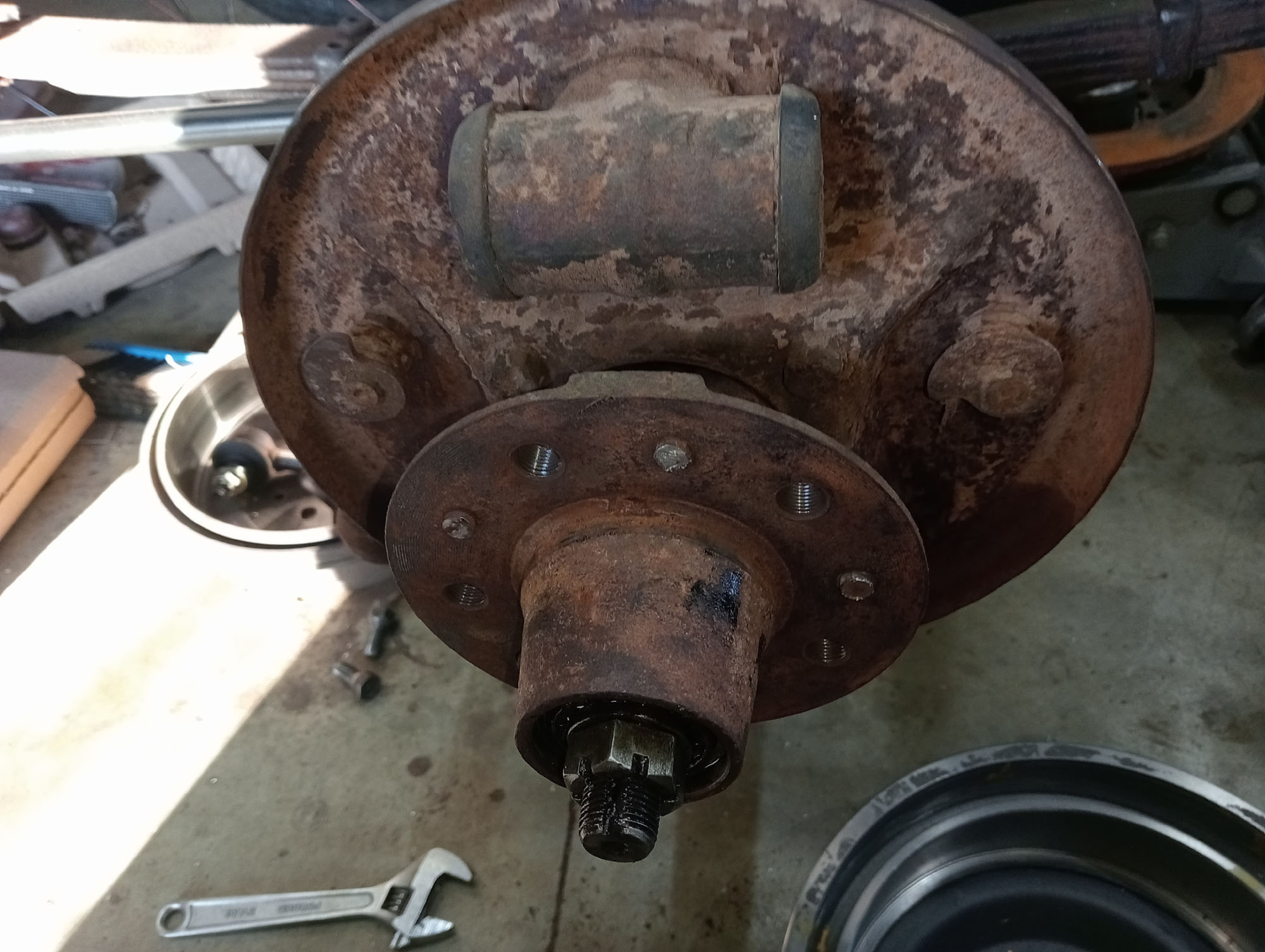
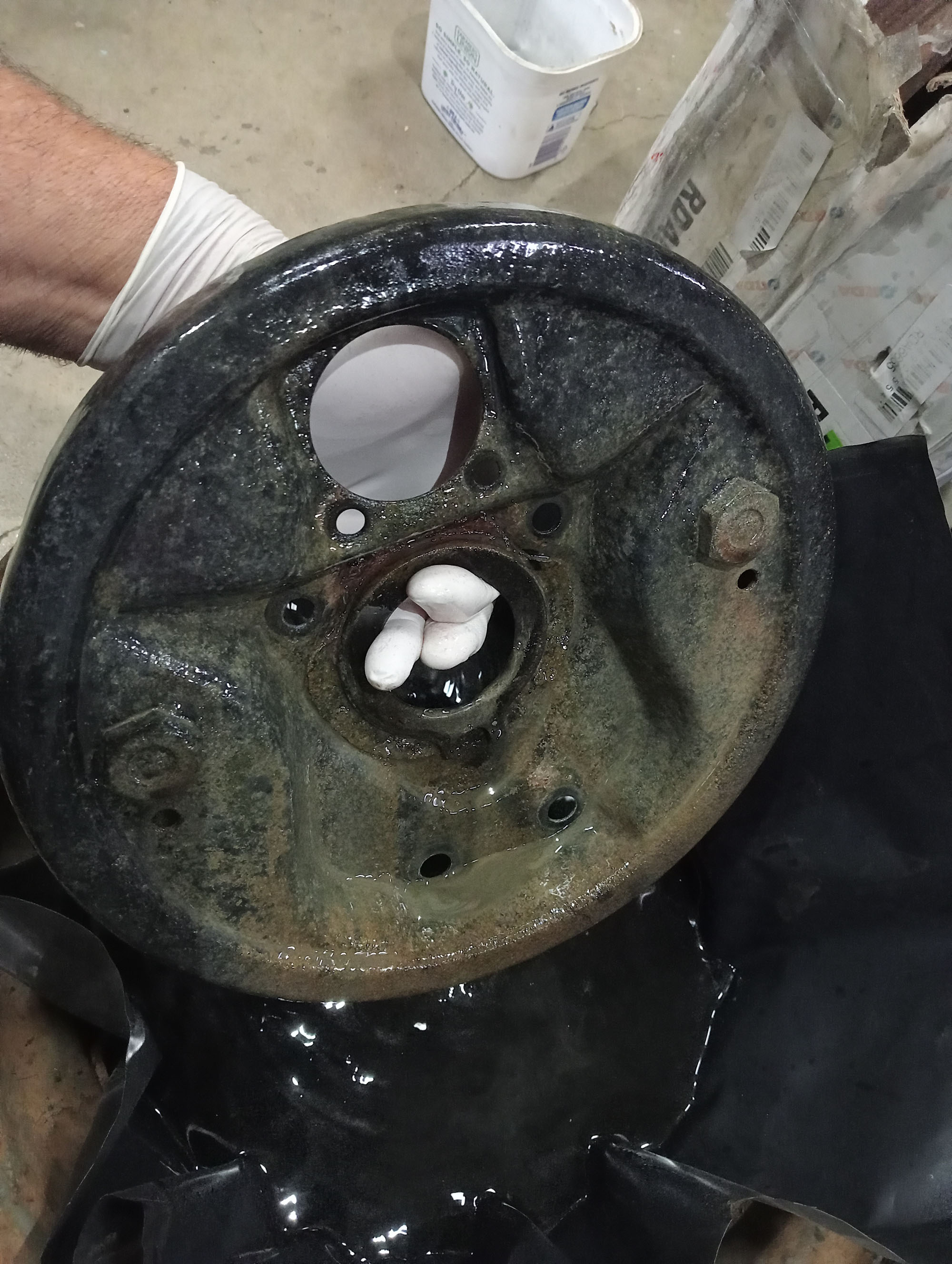
The rear is easy, The Hilux Axle ( with 15/16" slave cylinders) has new shoes & drums fitted , I replaced the drums with new as they had a step worn in, normally a non issue , except for a RWC its easier if the tester can just pull the drums for their photo without frigging around with the adjuster.
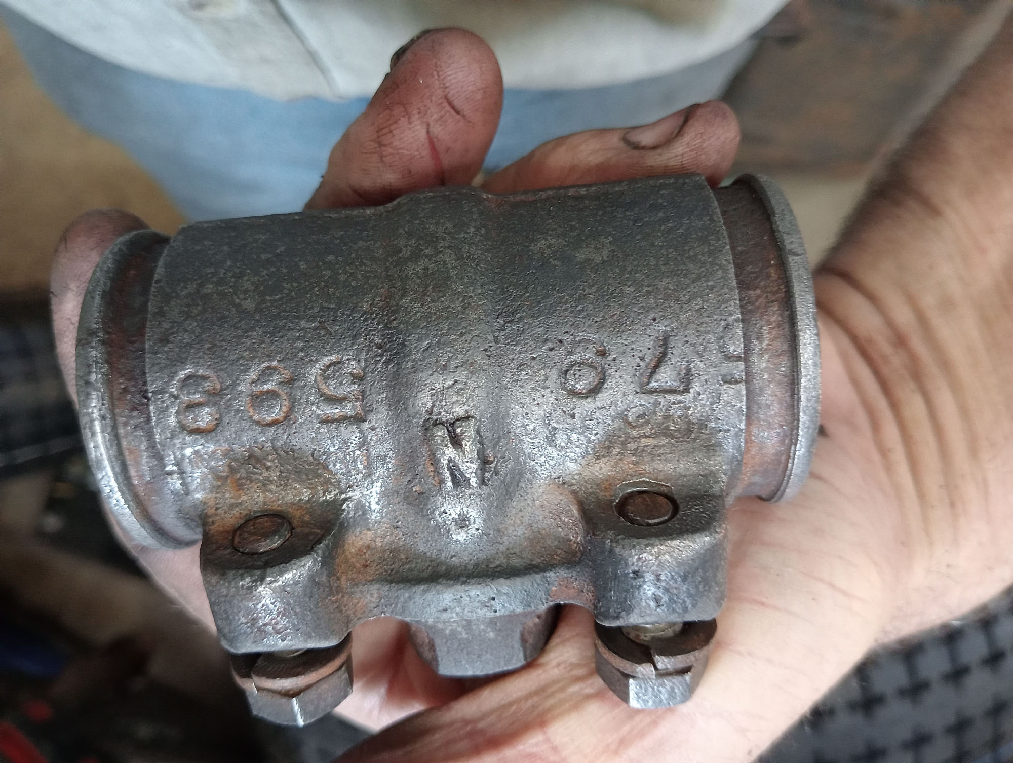
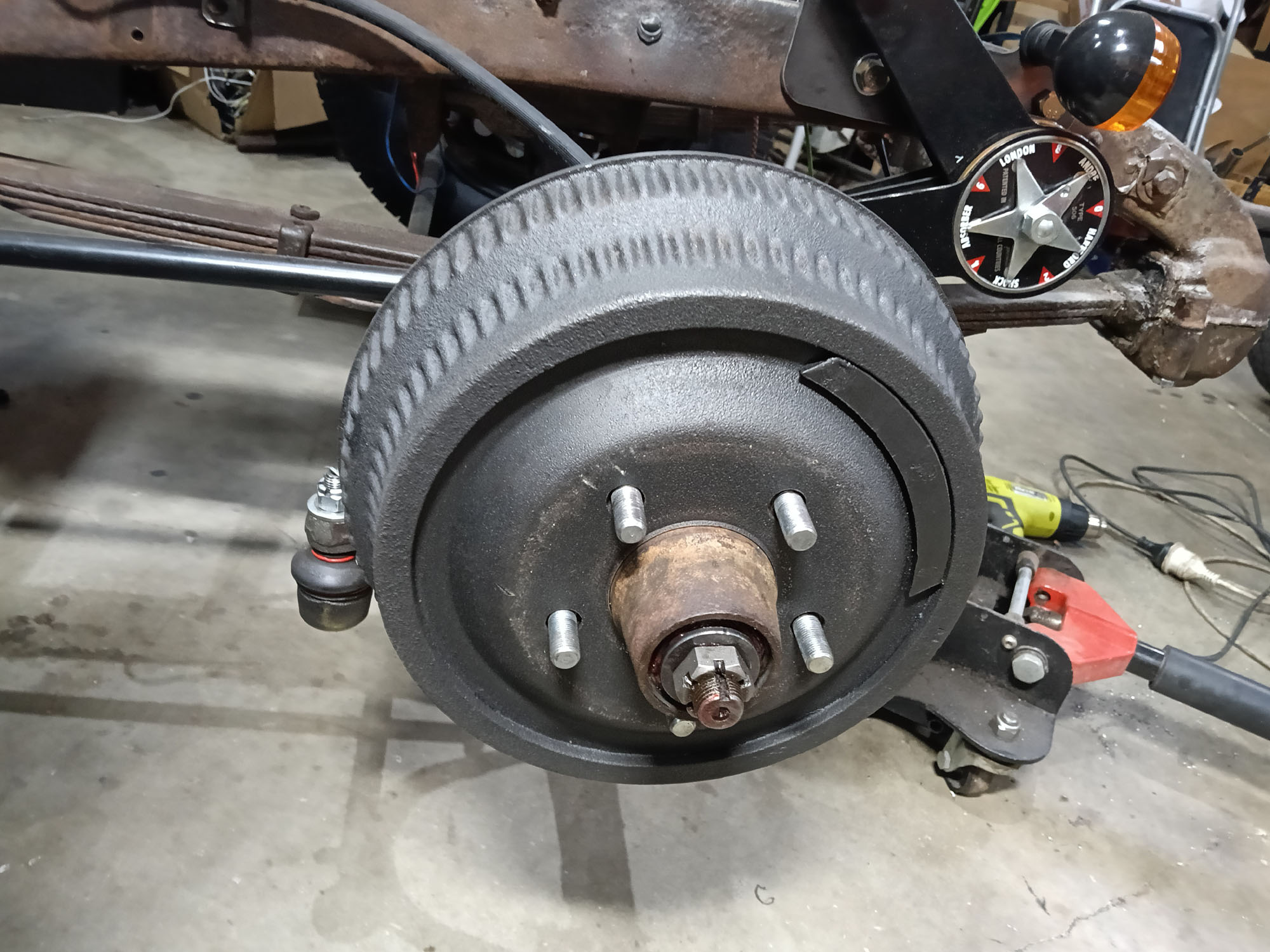
Front brakes are the 3/4 Ton Fargo Truck Brakes that came the farm fresh donor chassis. (3/4 ton refers to the cargo , not the weight of the truck) The early Fargo brakes have stepped slave cylinders with 1-1/4" & 1-3/8" pistons. The asbestos shoes were down to the rivets and brake drums were un-serviceable. Brake drums for old Chrysler's are a problem which is why its easier & cheaper to convert to Discs, Up until recently the 10" drums have been unavailable but recently being re-manufactured in USA for US$500 each , plus shipping , at todays exchange rate will cost you about AU$2000 for one set of boring 10" brake drums.
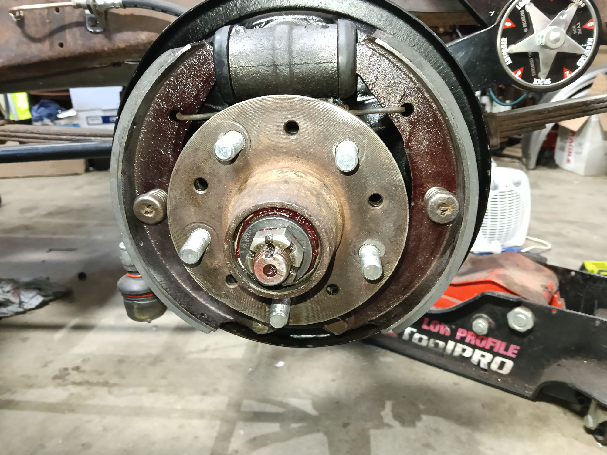
Not wanting to waste $2000 on some front drums I hit the internet groups with no joy , then PBR & Brembo catalogues looking for any close match. Obviously I first tried Hilux / HiAce drums because the 10" diameter and Stud pattern is the same but offset is wrong. Then other brands that have 10" dia & 5x4.5" PCD are Ford , Valiant , Jeep . Hmm Jeep . I drilled down into Jeep brake dimensions & bingo . 1999- 2008 Jeep Cherokee DBA1794 rear drums are a match - on paper anyway. Brand new drums on eBay special from a trusted Auto Parts supplier $80 a pair - That's EIGHTY DOLLARS so I jumped on them.
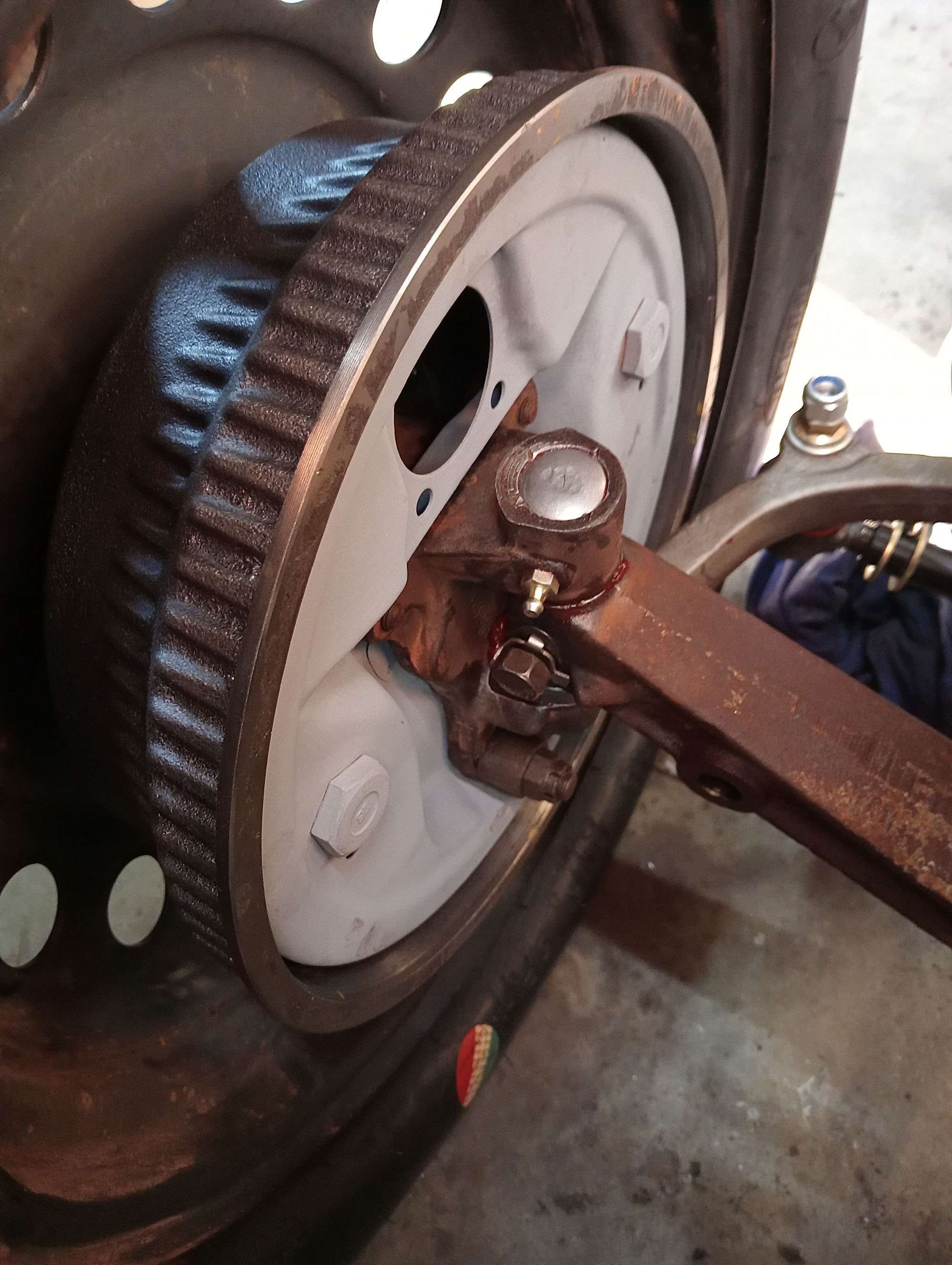
Could not believe when they arrived that they are ribbed drums (eBay picture showed plain drums) with an external raised part to 12" diameter. They look exactly like retro Buick 12" drums that Hot Rod builders covet. Some Rodders that convert to disc brakes even go to the trouble of fitting fake Buick drums over the discs& caliper to mimic drum brakes.- anyway this is THE look Hot Rod builders are after, even though, as I keep saying, I'm not building a Hot Rod
I was so impressed with the fit of the Drums that I bought another pair for $80 , crazy price but I'm not complaining. The are actually an interference fir over the Fargo front hub spigot, the original one are sloppy - this is better than I'd hoped - What I can't fathom is some place in USA is re- manufacturing new drums to sell at US$500 EACH when you can buy these for AU$80 a PAIR.
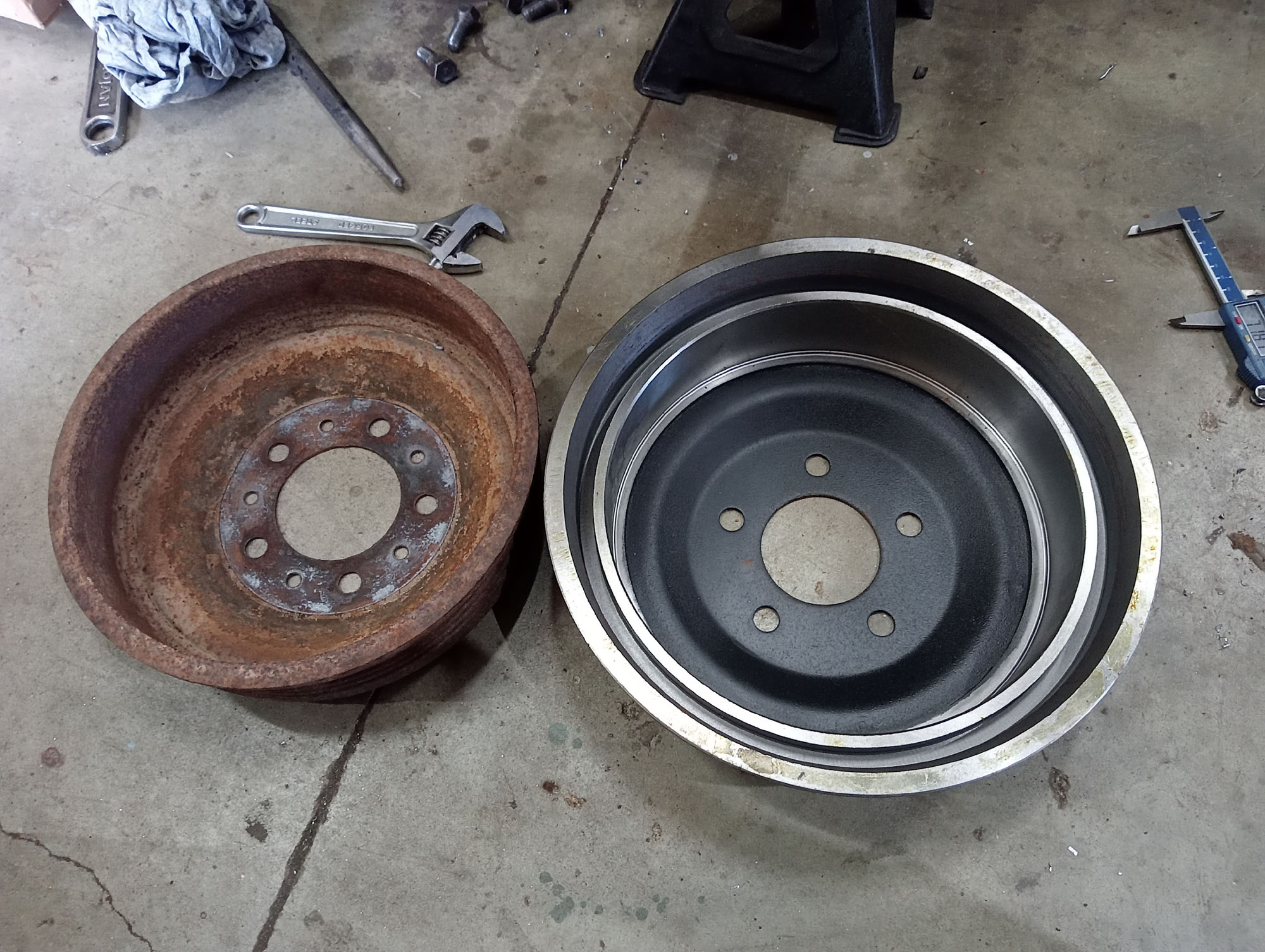
Original drums vs Jeep drums , yes they look a lot different , but the critical dimensions are what matters, Center Hole / PCD / drum internal diameter & height are a perfect match to the Dodge hubs.
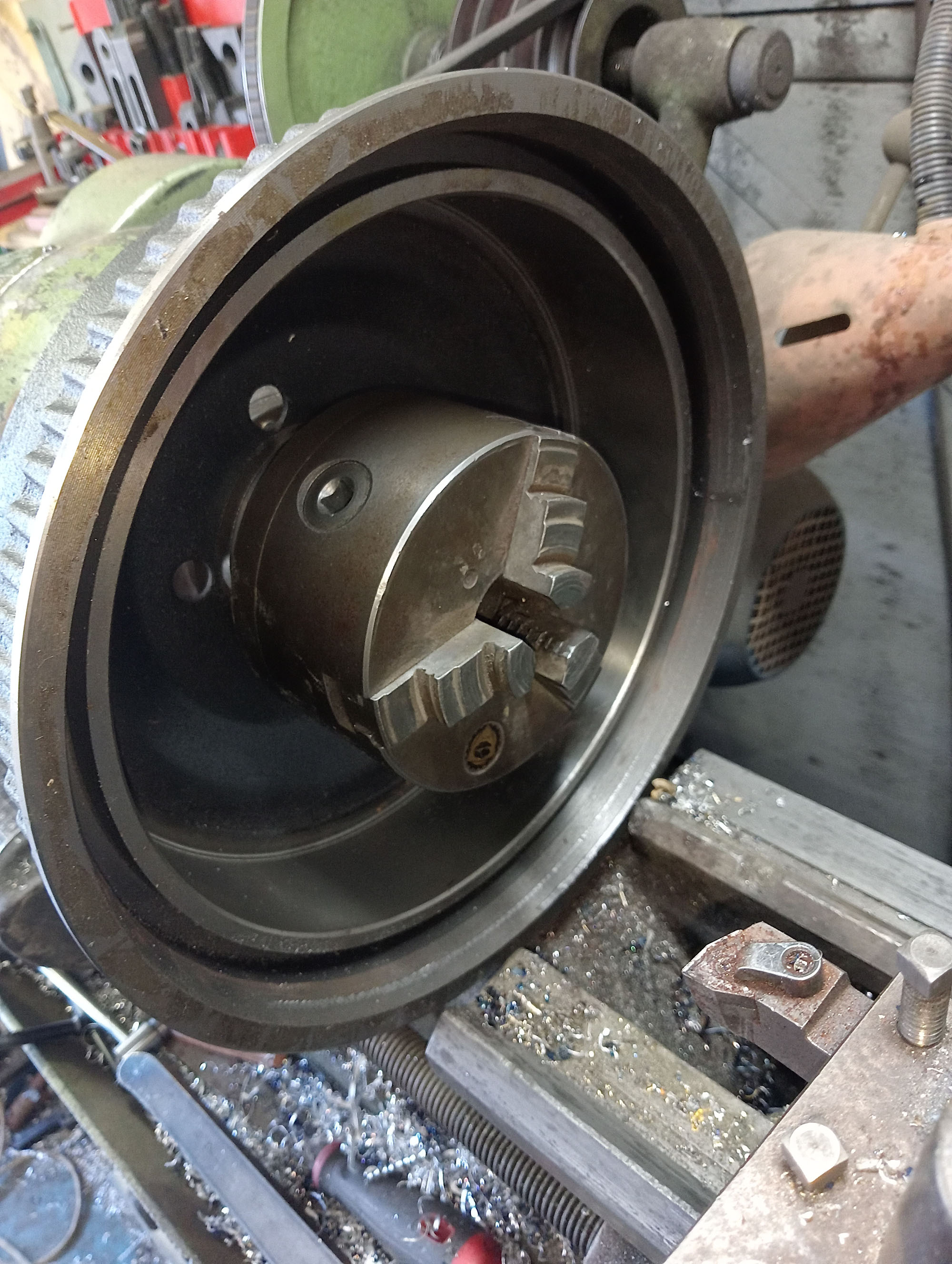
I had to skim some material from the groove that fits over the Jeep backing plate, only way I could mount the drum on my small lathe was to clamp it behind the chuck - not recommended but hey, if it works its not stupid.
Rusty slave cylinders were left to soak in some Evaporust overnight, Evaporust is expensive at $100 a gallon but worth its weight in gold. These cylinders came out looking almost new, I was able to pop the pistons out with compressed air (instead of the usual grease) Pistons were good , just needed a hone & new rubbers.
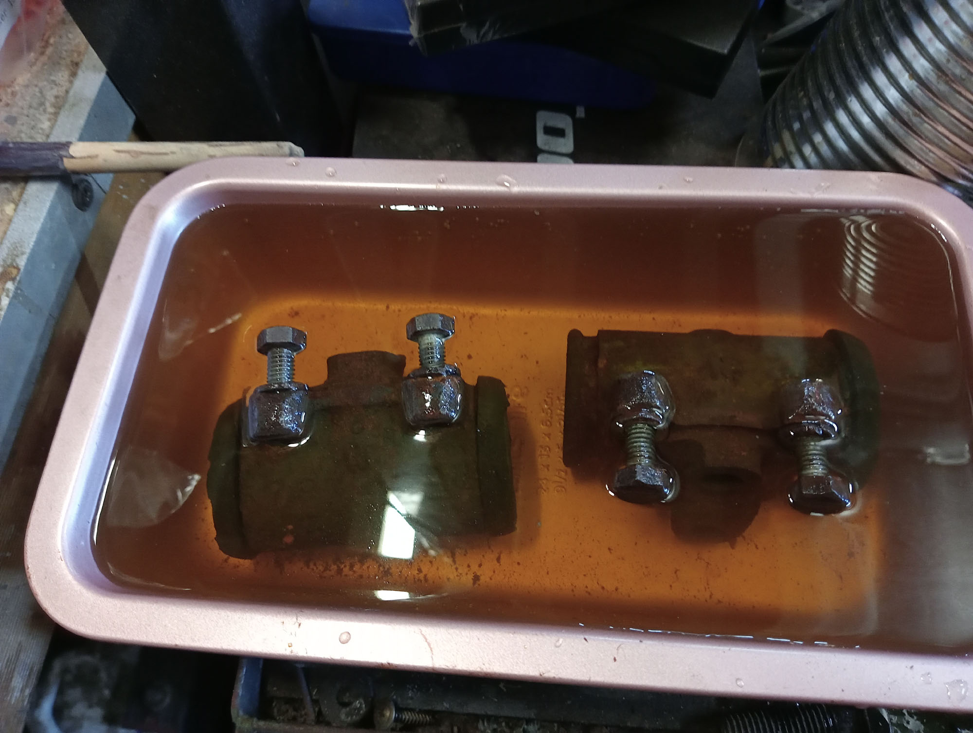

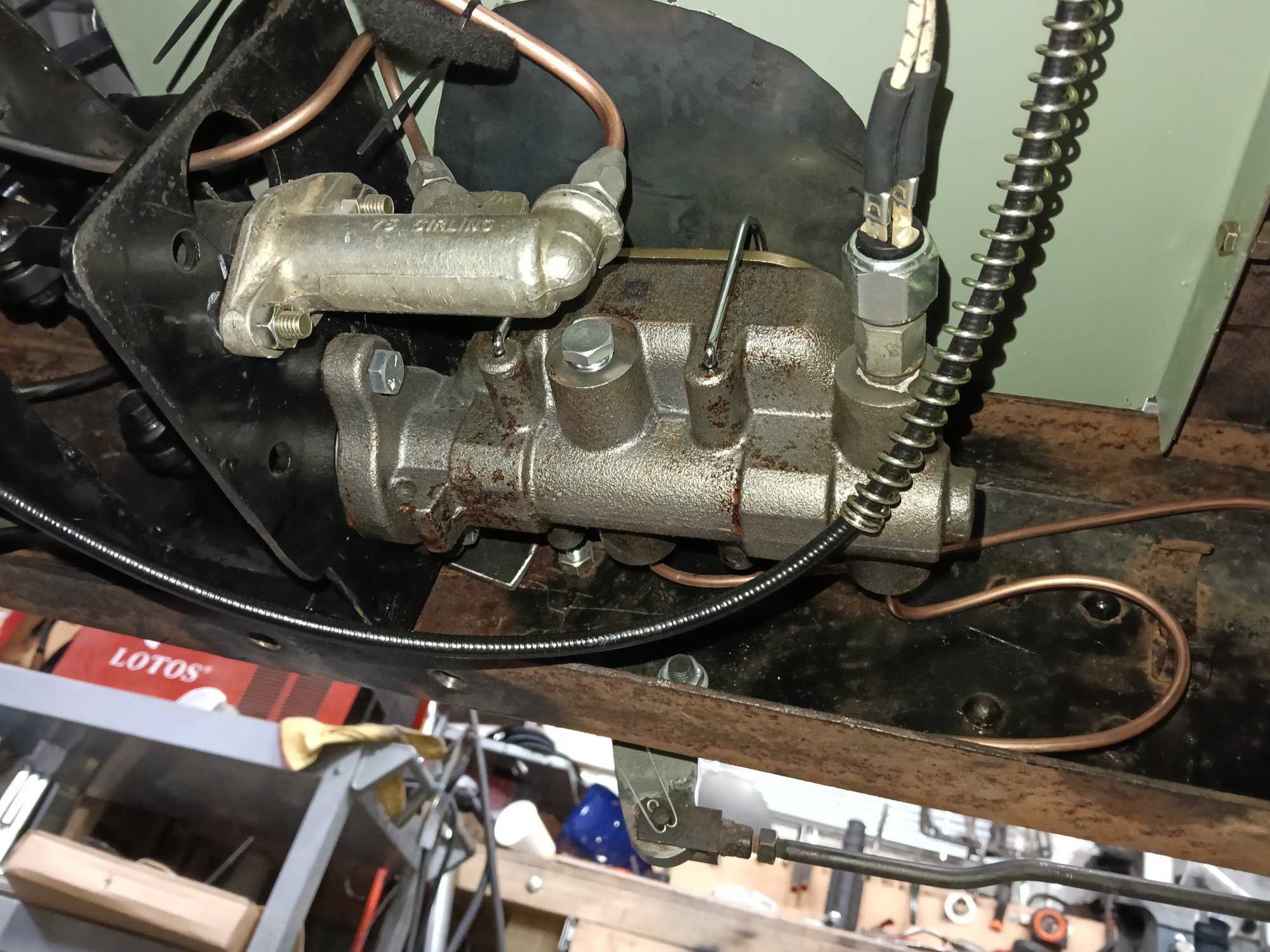
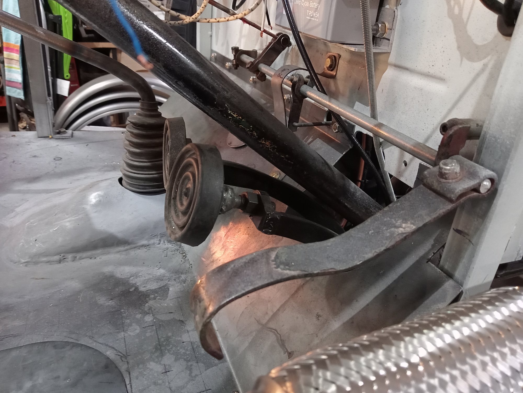
The brake master cylinder is a non boosted 1970's GM style 1" dual master cylinder mounted under floor in the gearbox cross member with an early Ford style pedal set up , The hydraulic brake switch is in a spare outlet port on the front circuit.
The other cylinder in the photo to the left of the brake master cylinder is a 3/4" Land Rover clutch master cylinder .
Handbrake lever was covered earlier, It operates via a Land Rover Series 2 handbrake pushrod onto an arraignment to transfer the action to the inside of the chassis where a linkage provides an equal pull on each rear wheel handbrake cables. These are shortened Hilux Cables. Some kind of balancing mechanism is a legal requirement on any car with cable wheel brakes, or handbrake.
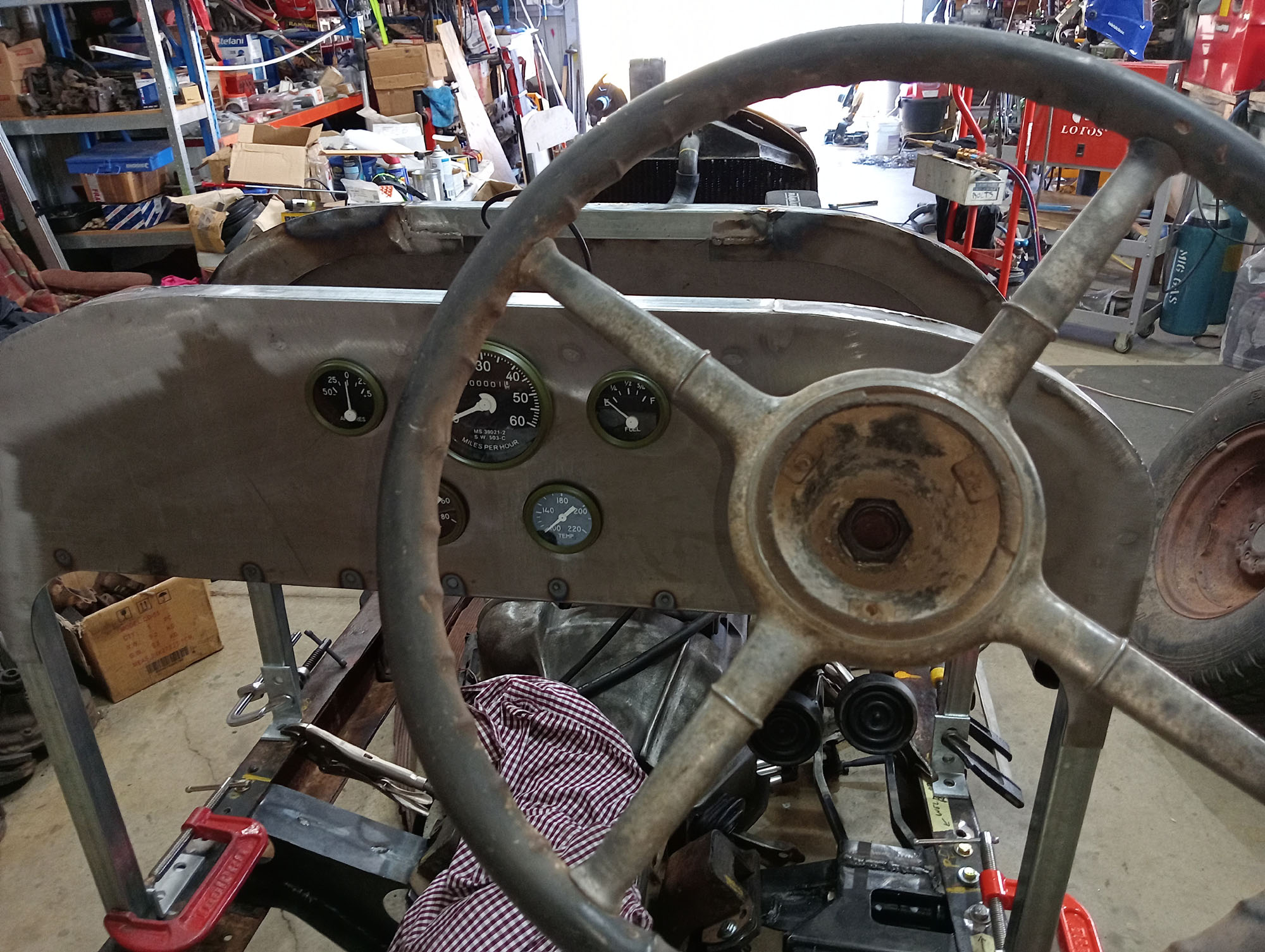
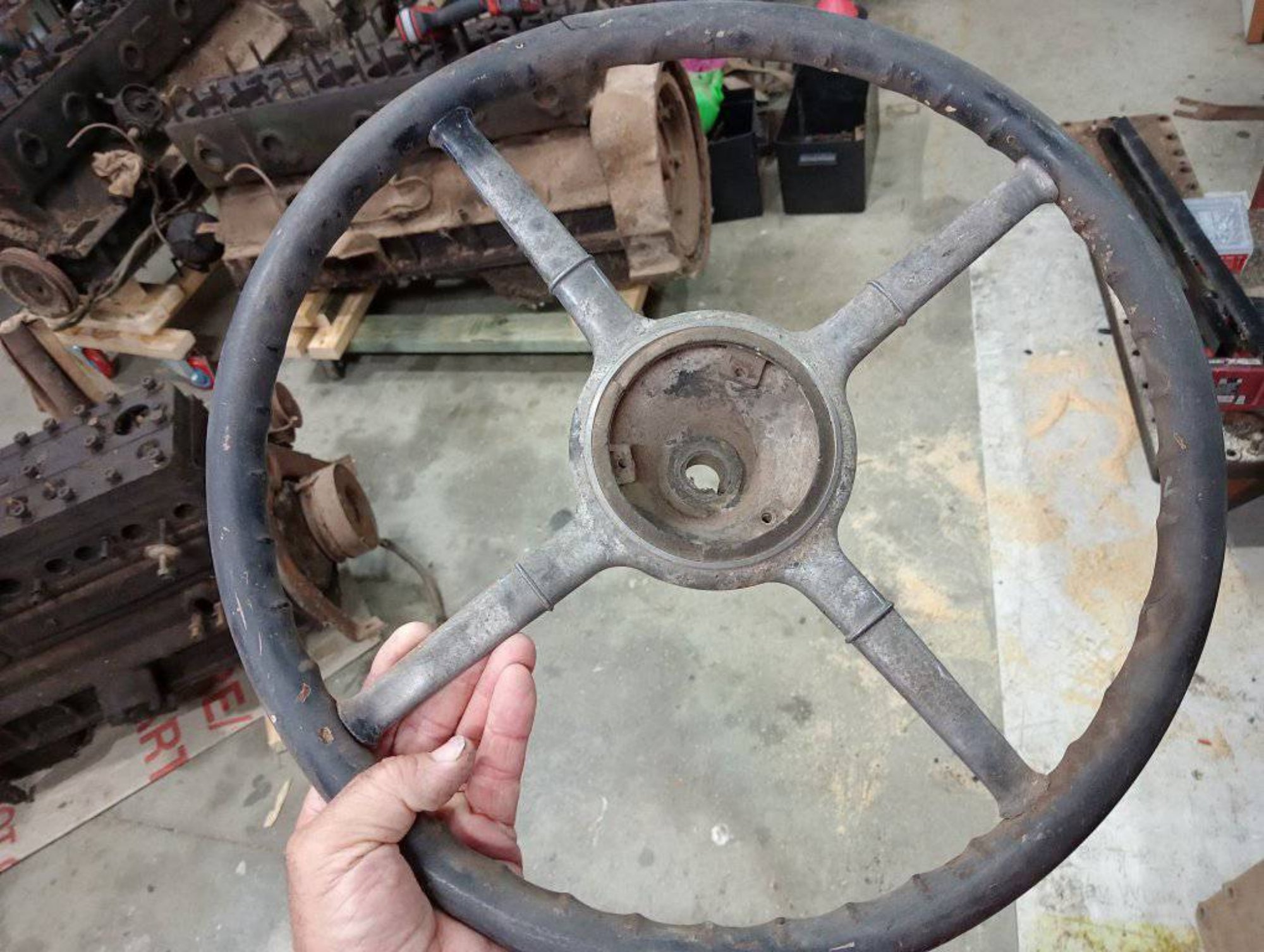
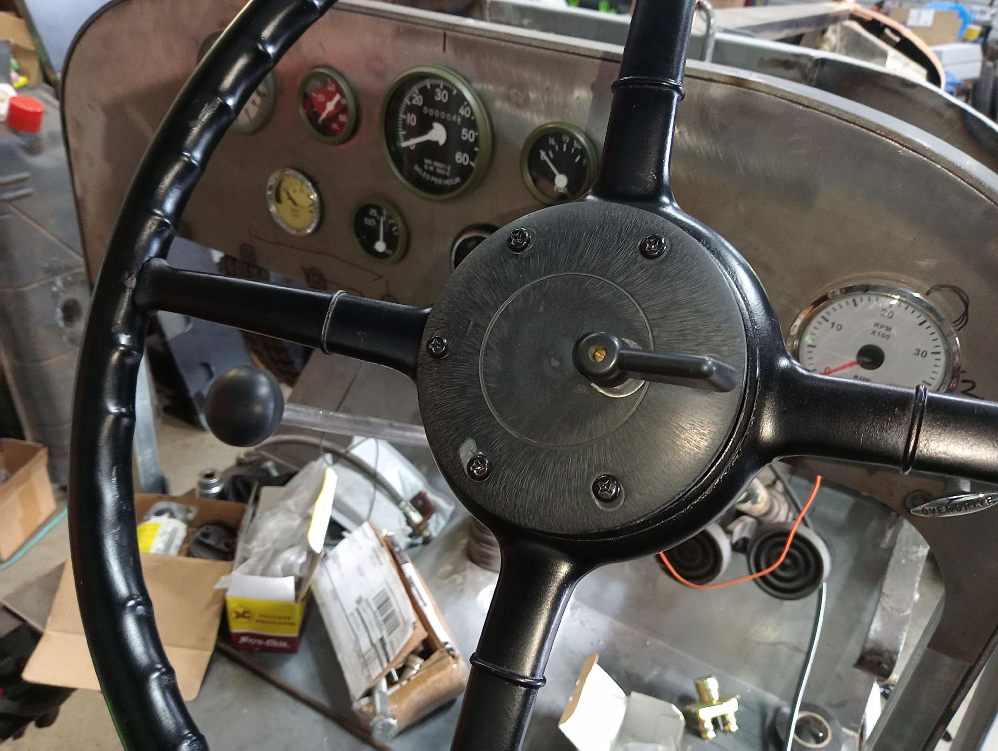
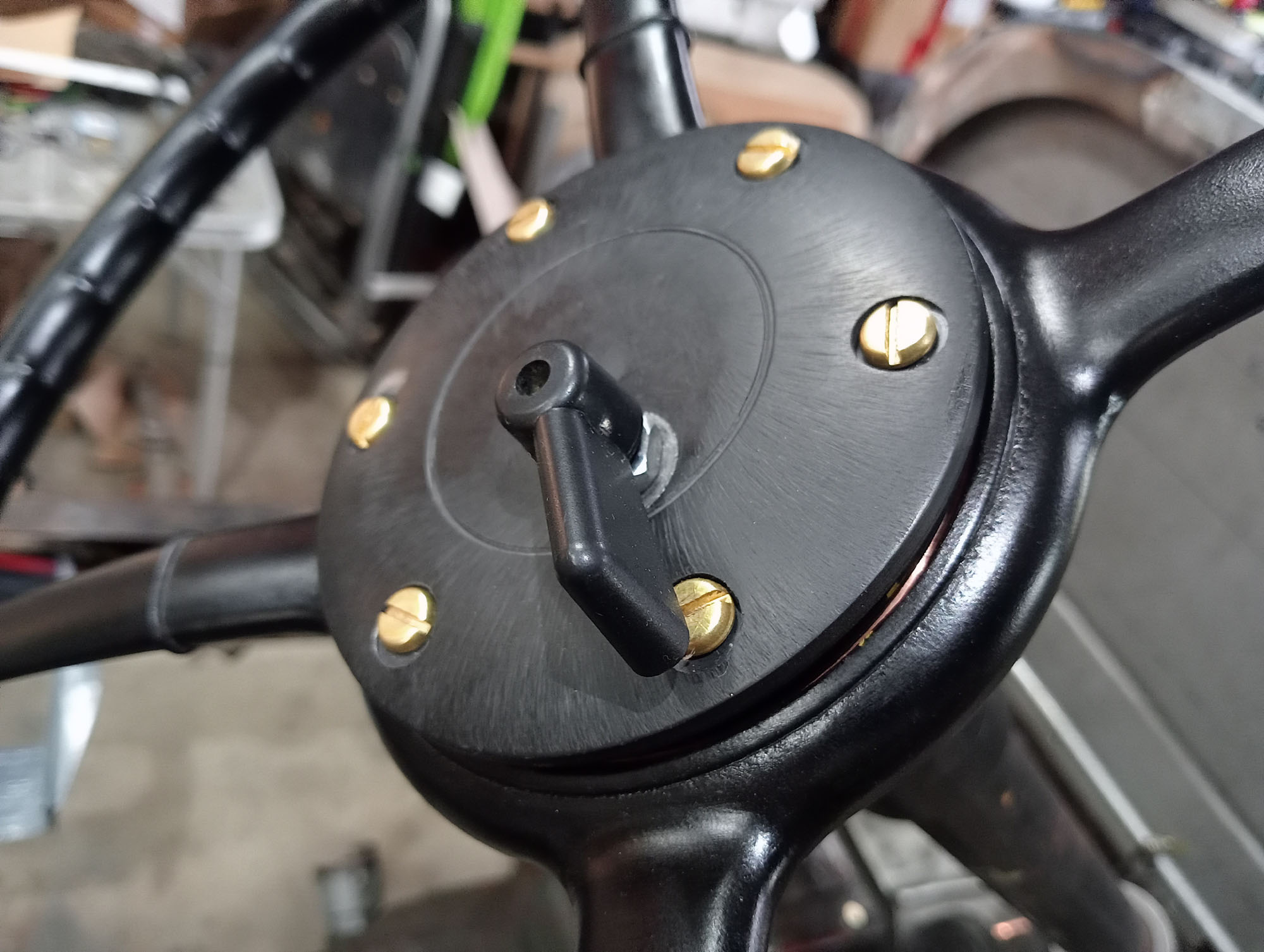
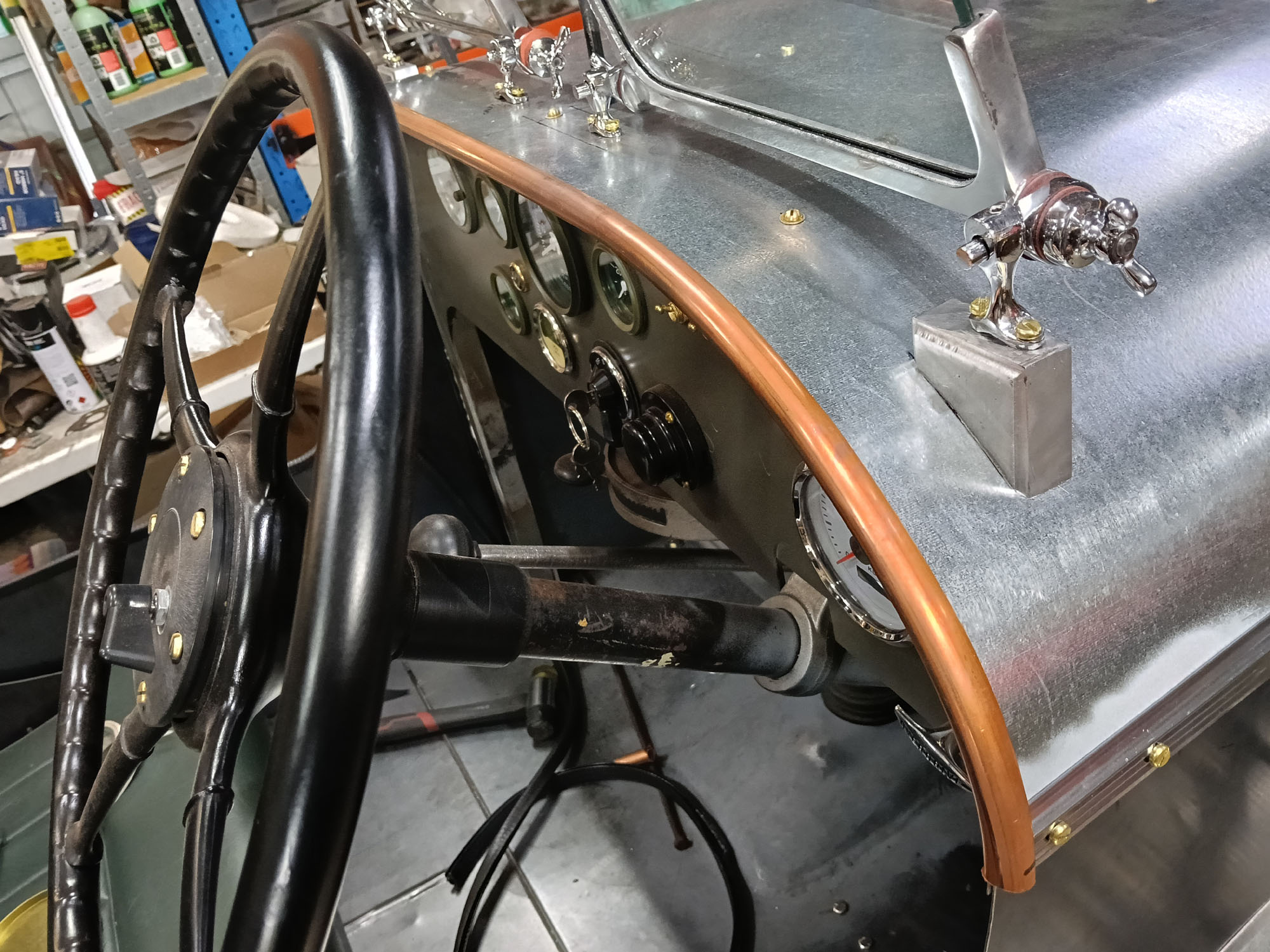
Steering wheel
One of the first things I did once I realised I was building a Speedster was to draw up a 18" diameter 4 spoke steering wheel in CAD. The plan was to plasma cut the spokes & rim band, machine a hub from billet and make a wooden rim. Then this unknown early 4 spoke wheel turned up on eBay, Seller didn't know what it was from, nor did I.
Dropping a photo onto a vintage car group provided the answer - Its a 17" wheel from a 1931 Buick.
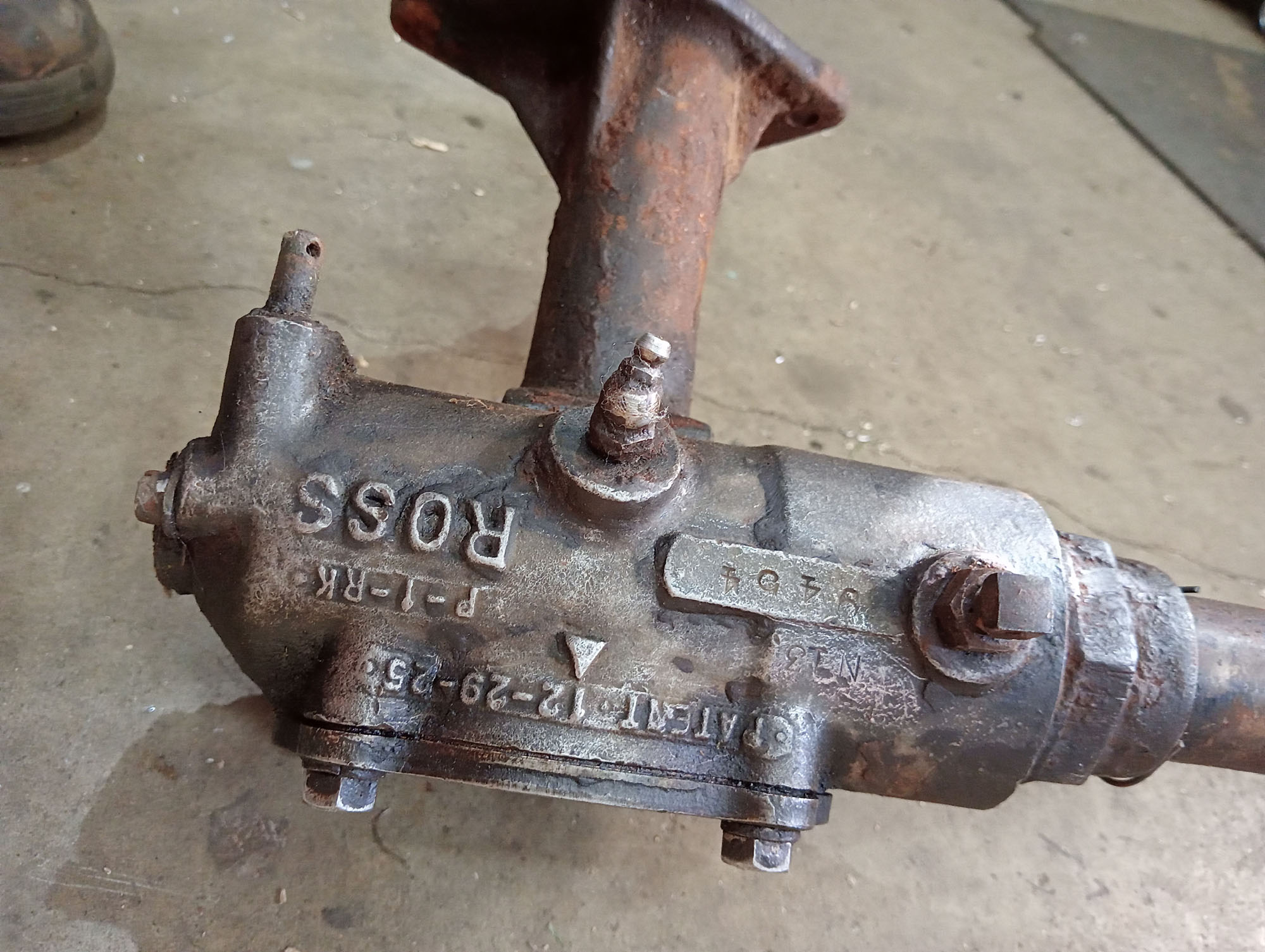
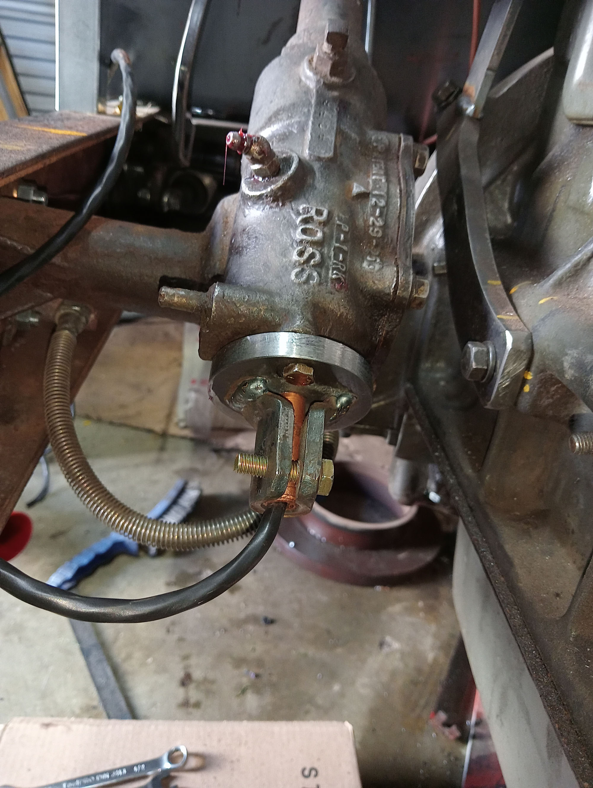
I picked up an unknown Ross steering box with a 1925 patent, Only 2-1/2 turns lock to lock - so will be quick steering , some research uncovered the Steering box is most likely from a 1928 Graham.
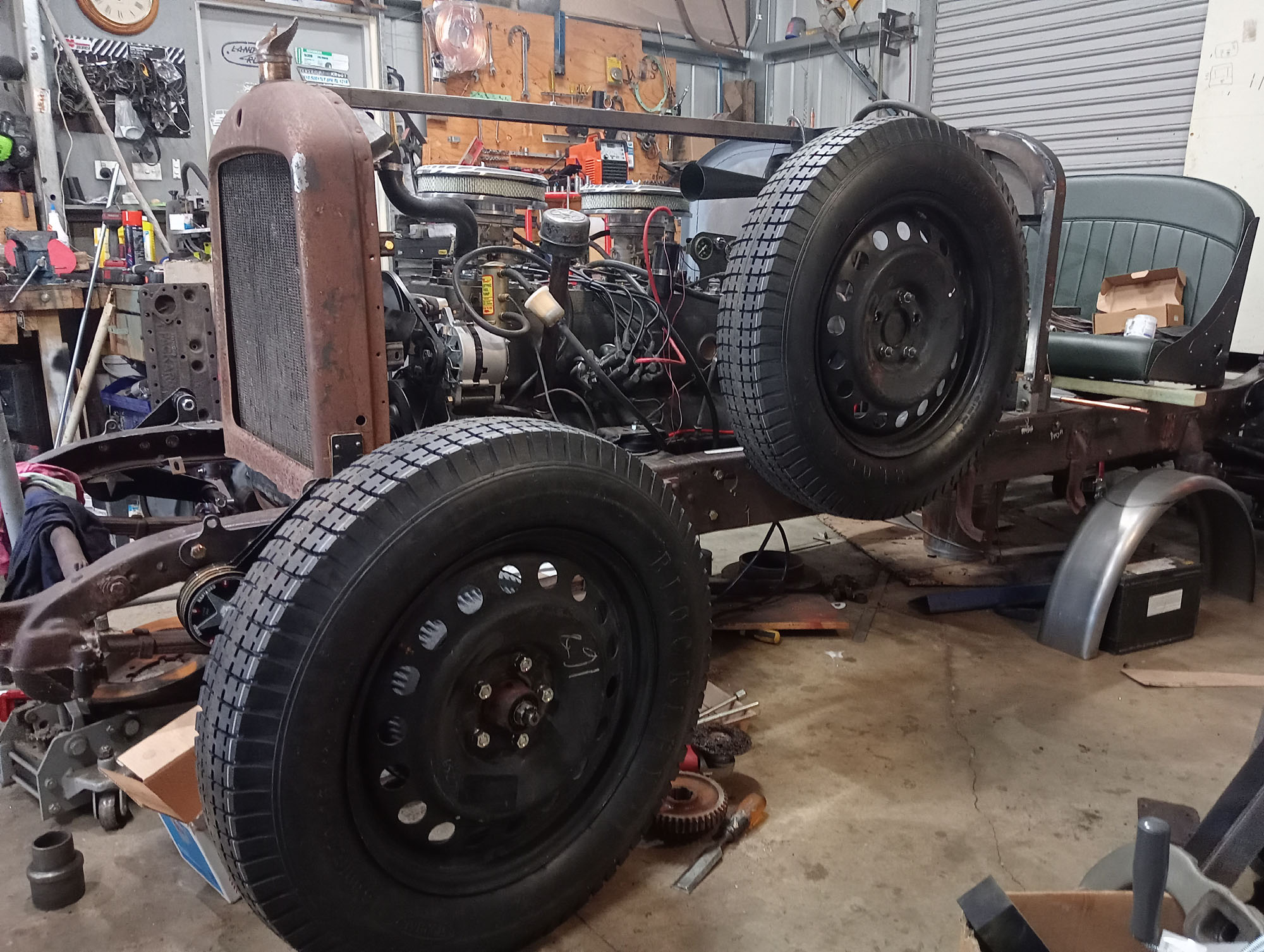
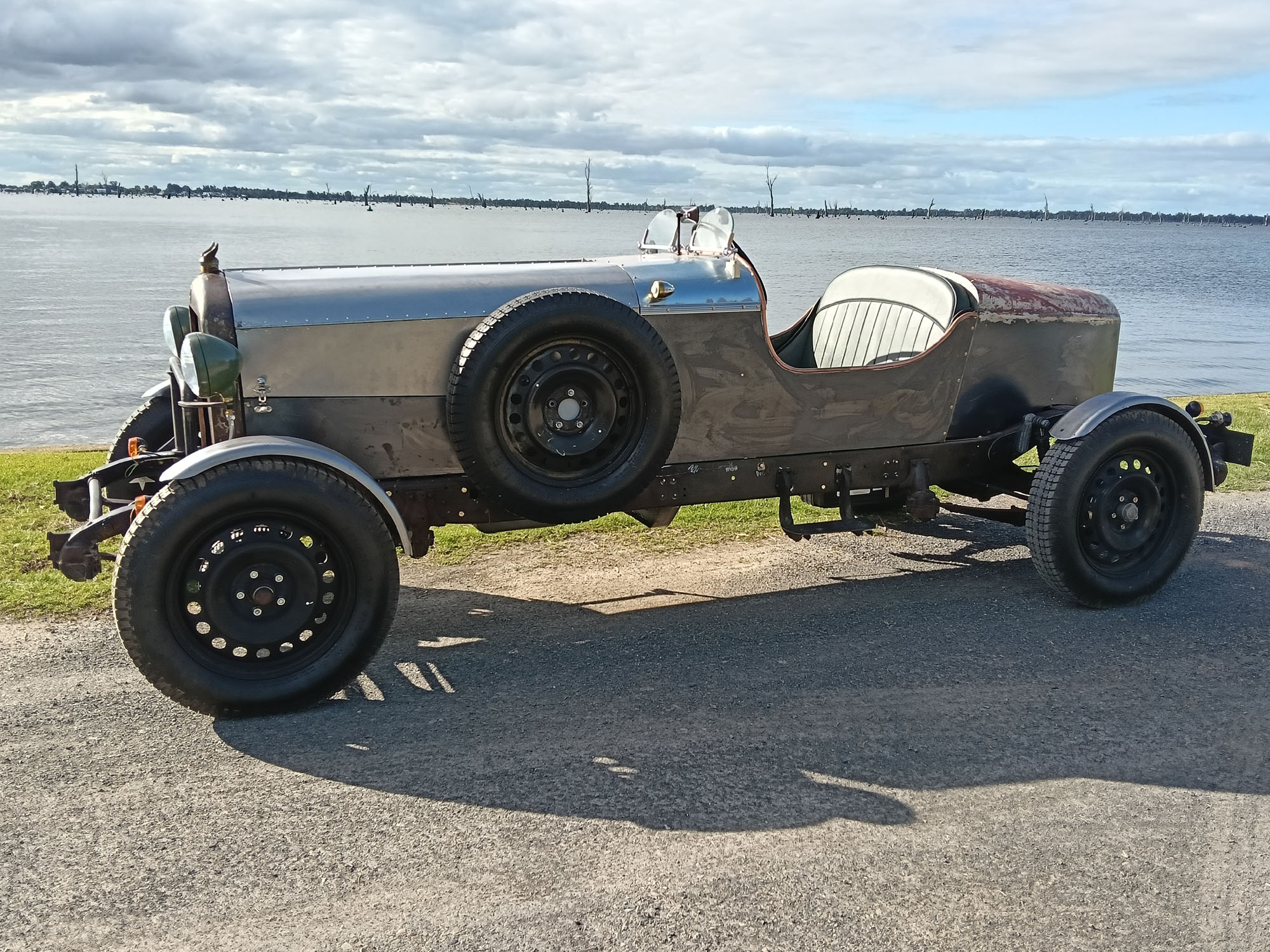
Wheels & tyres
Lets face it, this is not a very practical car, When you think about, does it even have a purpose? Probably not, it just has to look right. And to look right it has to have tall skinny tyres. As I said before, its not a Hot Rod, they generally run modern wheels and radials with bigger or fatter tyres at the rear & smaller or skinnier tyres at the front.
To look right the car has to be correctly proportioned , and the wheel & tyre size is critical. The original big Chryslers of this era had 550-18 tyres on 18x4 spoked rims, the Railton replica in this photo has 650-18 tyres (31" tyre diameter).
I had some Fargo 16x4.5 rims, and with 750-16 tyres the overall diameter is correct , if a tad wide and probably would look in proportion, but nearly all avaliable 750-16 tyres made today are for 4x4 or Vans and the load rating is way too high for a car like this, therefore no flex in sidewall giving a rough ride and poor handling.
I tried some Ford / Dodge pattern 17" wire wheels which looked nice but they would not fit over my brake drums, so then I thought about 17" Front-Runner wheels and Nankang tyres but the overall diameter was only about 29" , then I discovered modern Chrysler 300C Space saver spare wheels were 18" diameter x 4" wide , Had the right stud pattern and center hole matched my Fargo hubs , So I picked up 5 from a wreckers for scrap value.
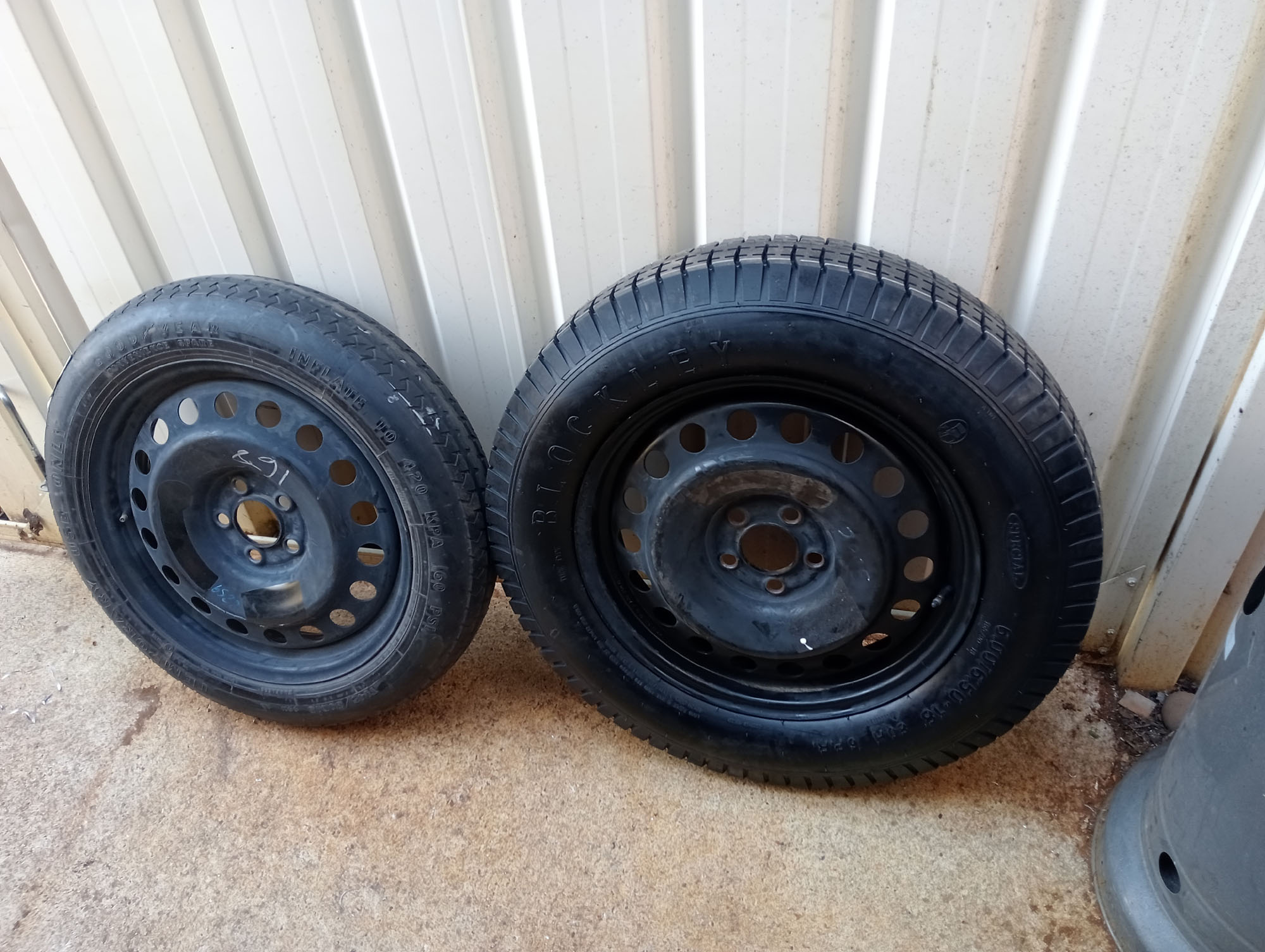
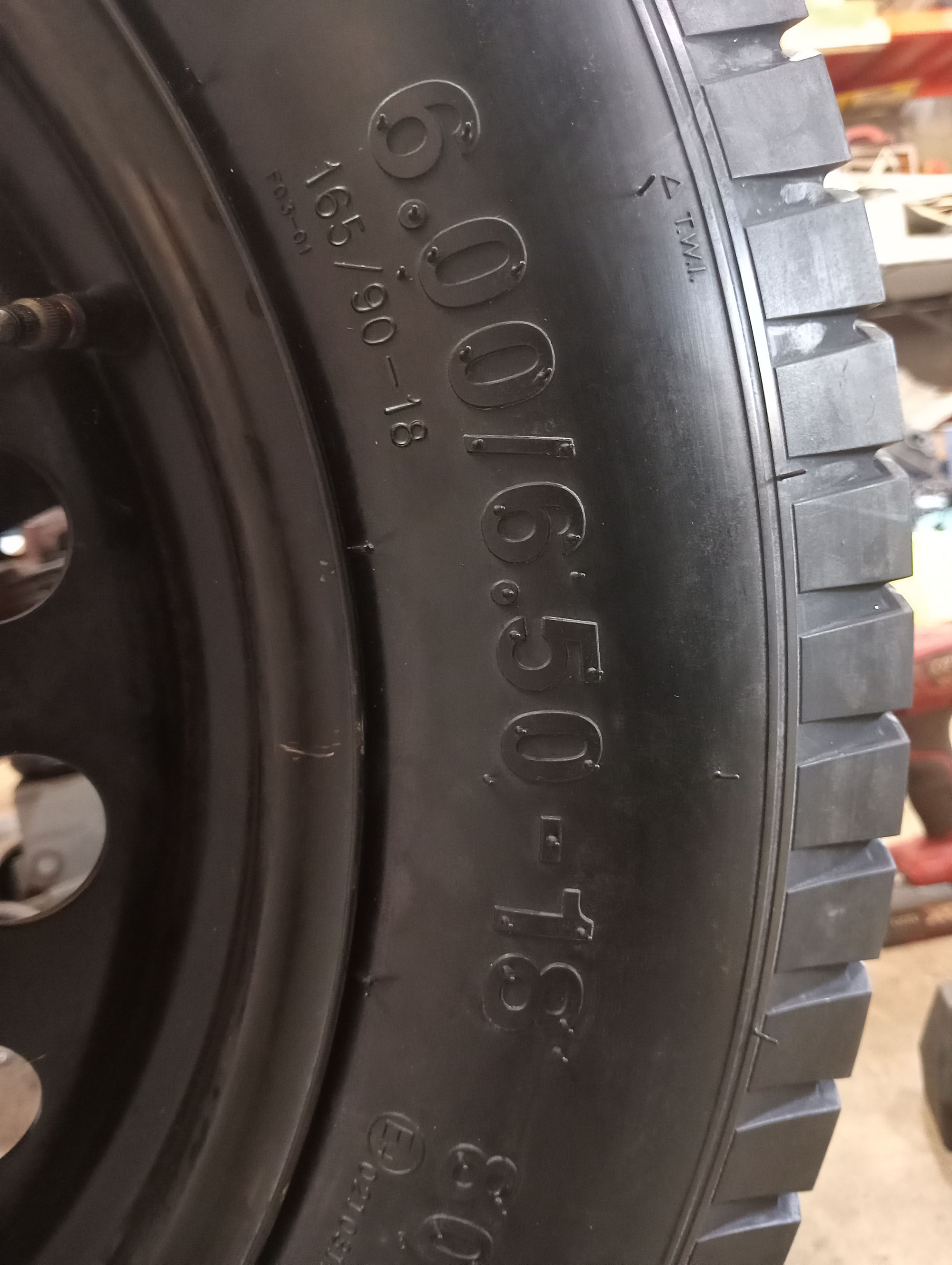
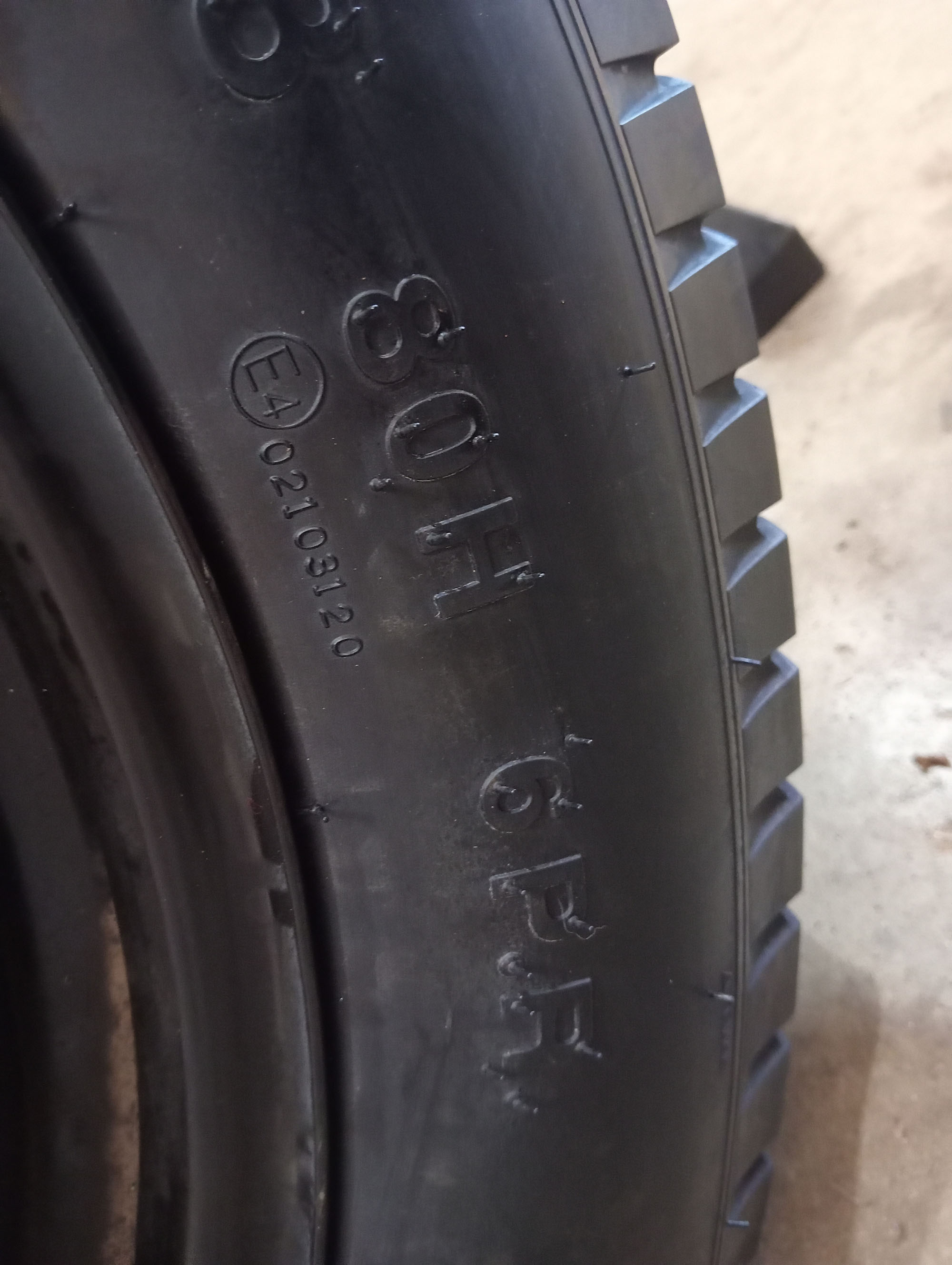
The Space saver wheel at left with its 80kmh speed restricted "Temporary Spare" tyre , almost looks like a motorbike tyre. then the same wheel fitted with a Blockley 650-18 6 ply tyre. There are a few businesses in Australia that sell 'vintage' tyres and they are absolute rip offs. You can do a lot better buying mail order from USA or UK , Coker tyre in USA sell 650-18 in Excelsior brand & Blockley in UK sell their own brand , At the time of purchase the UK exchange rate was a lot better than USA & freight was about half so the Blockley for the win.

Electrical system & wiring
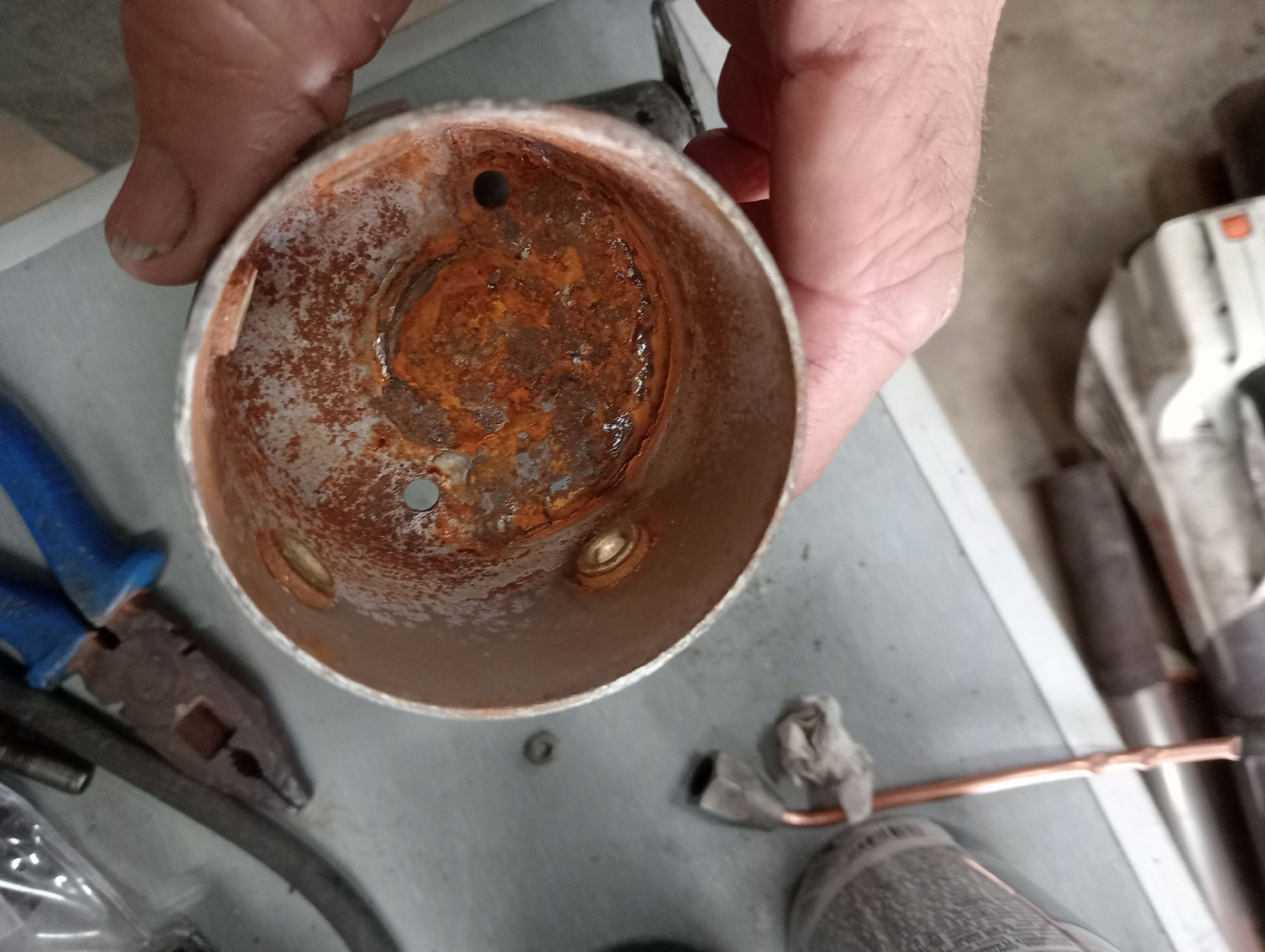
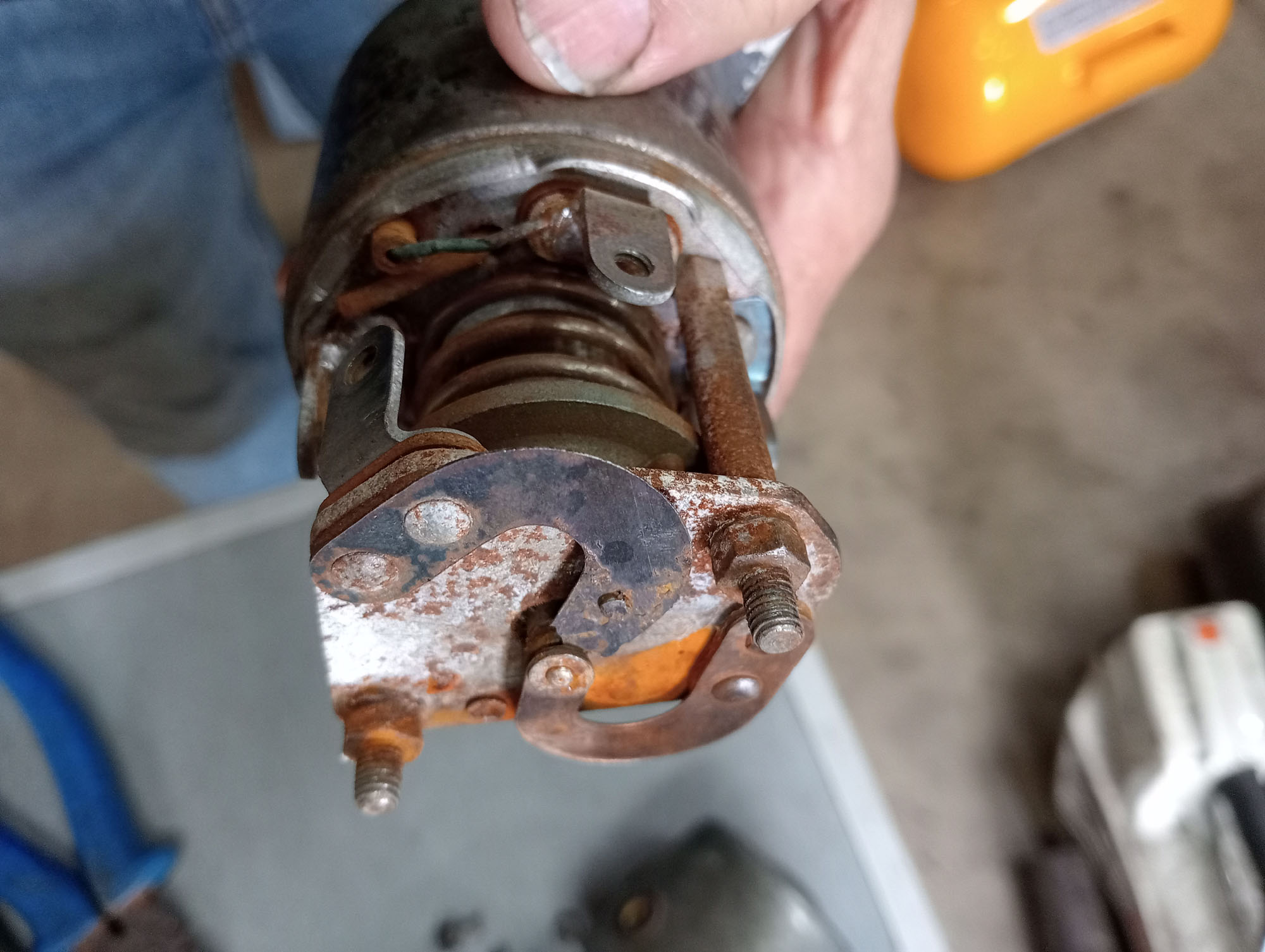
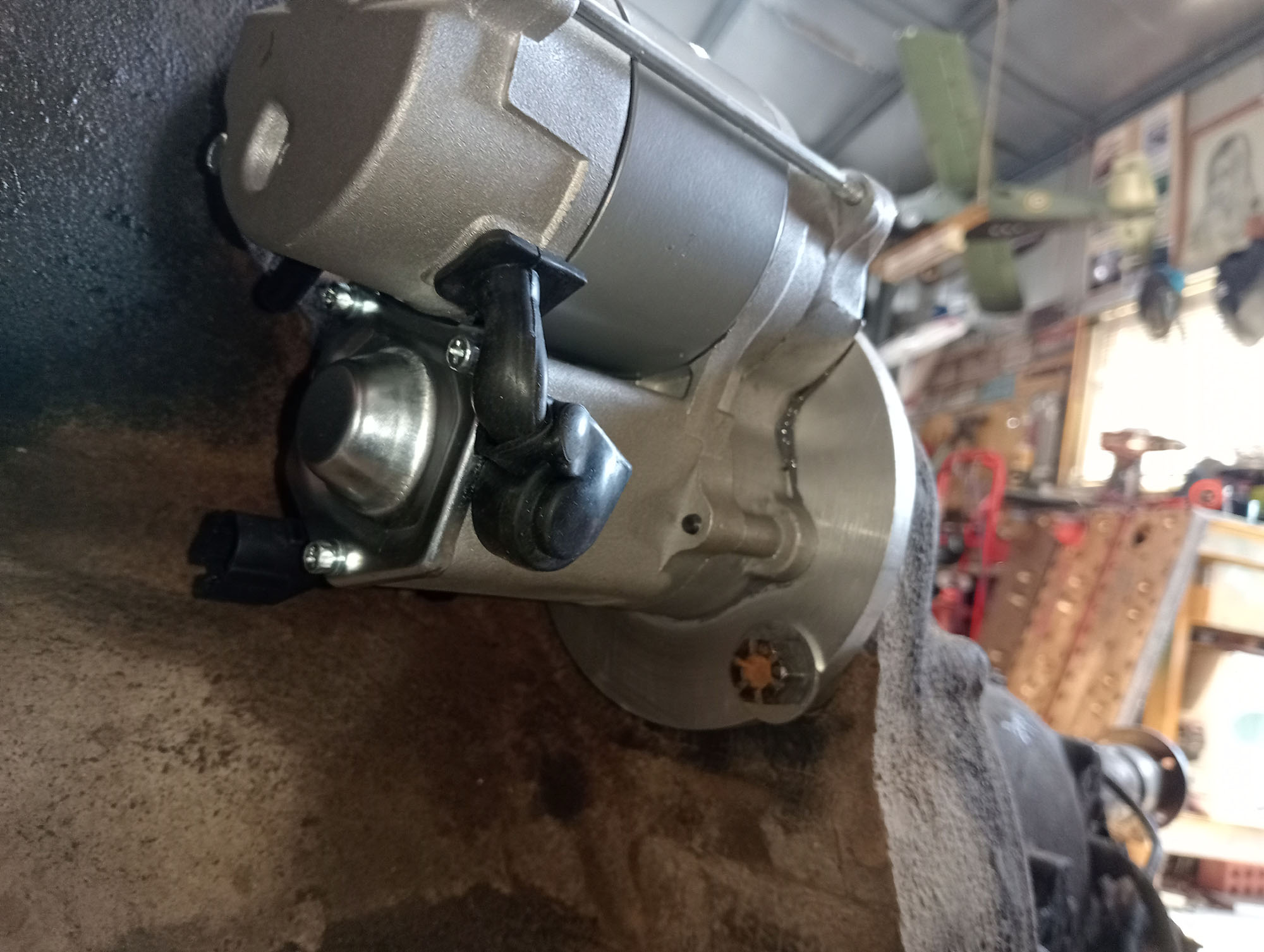
Starter motor
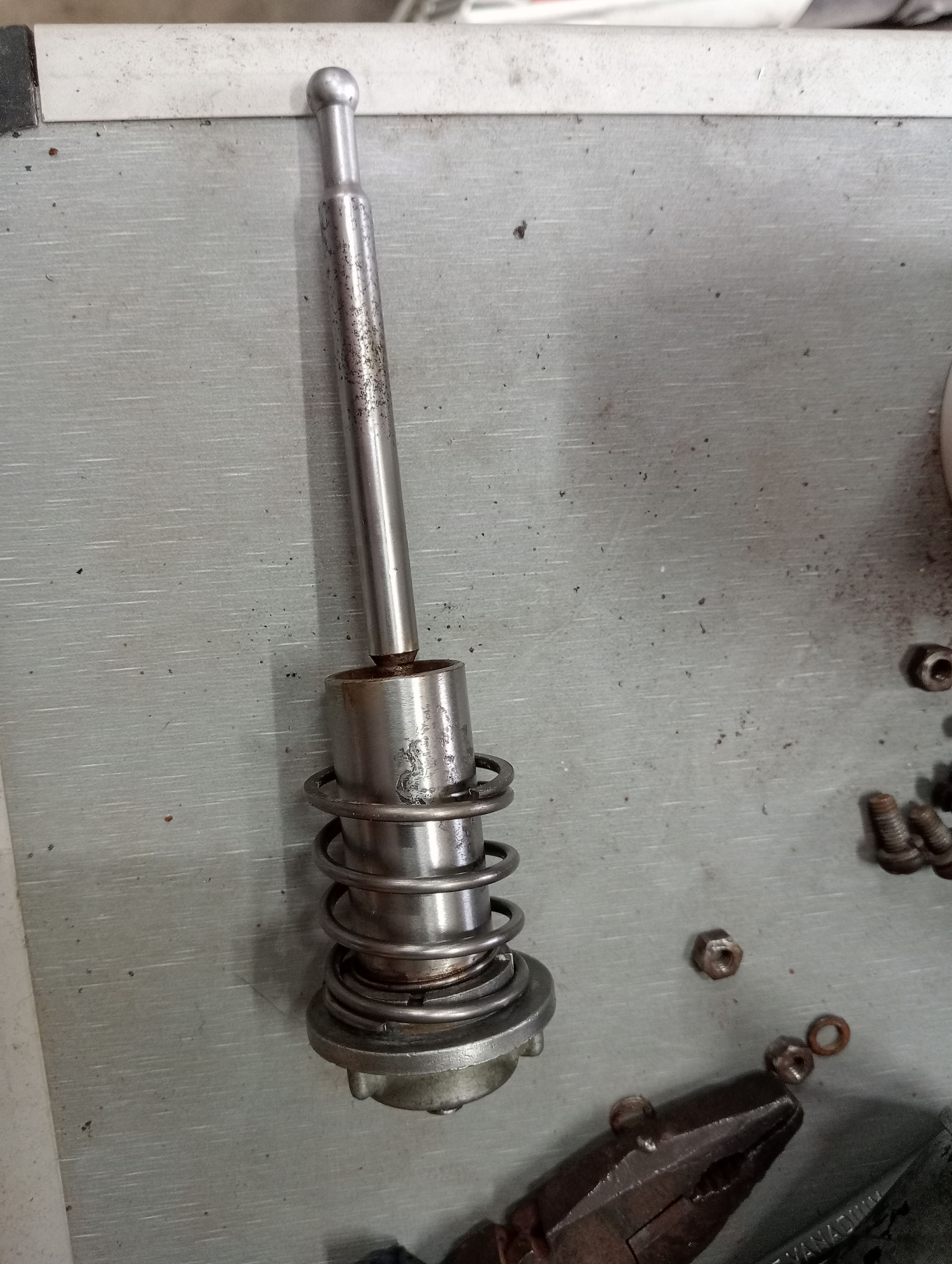
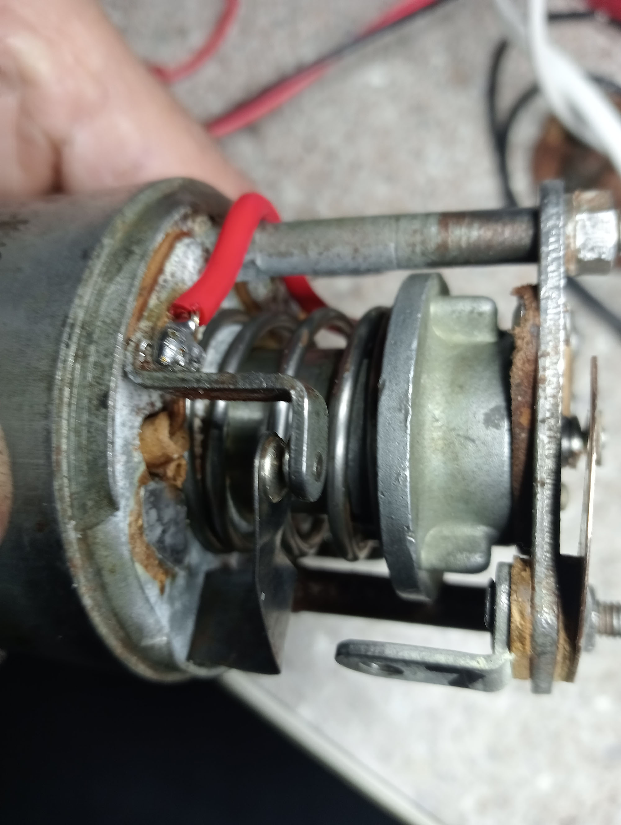
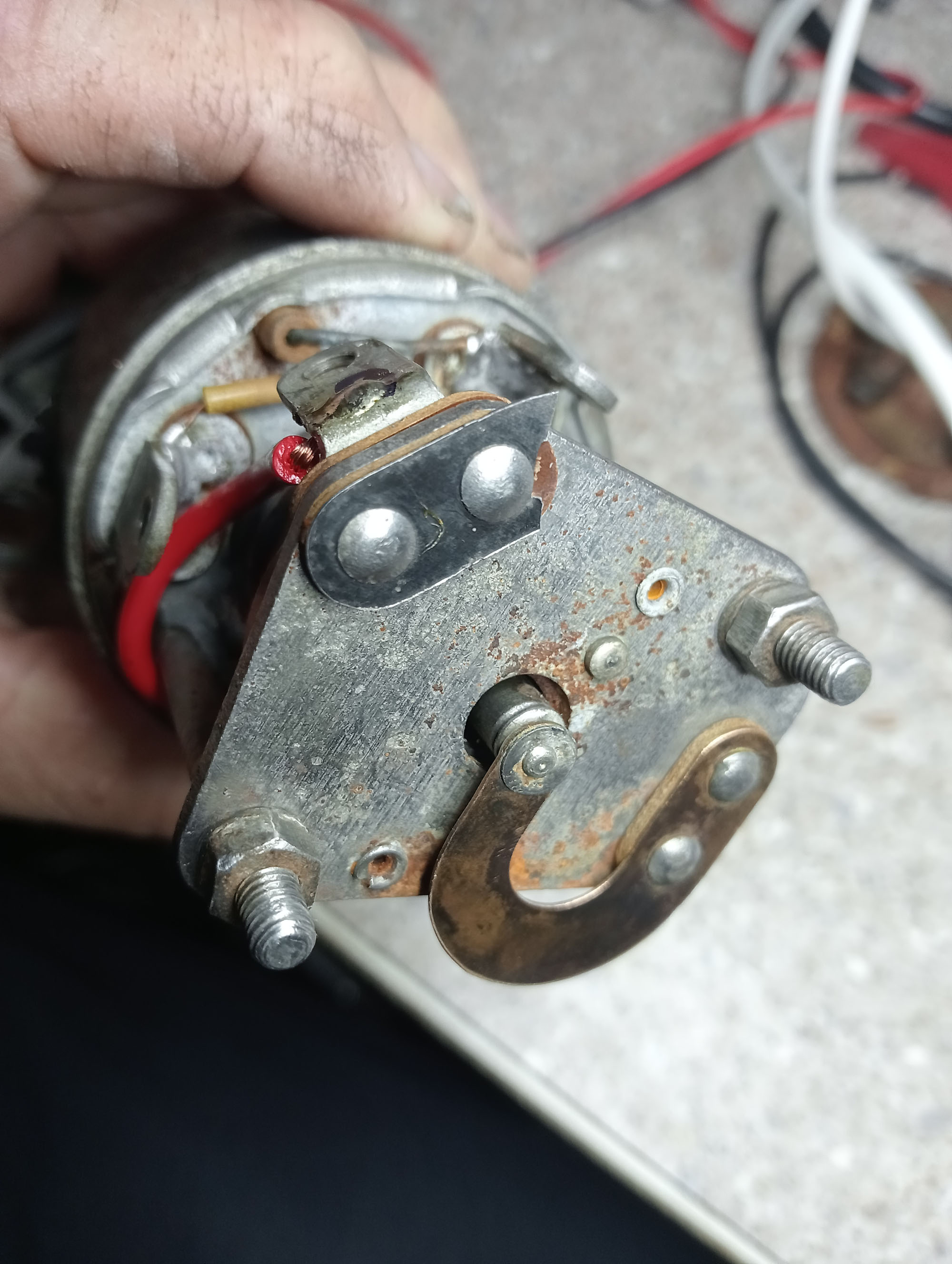
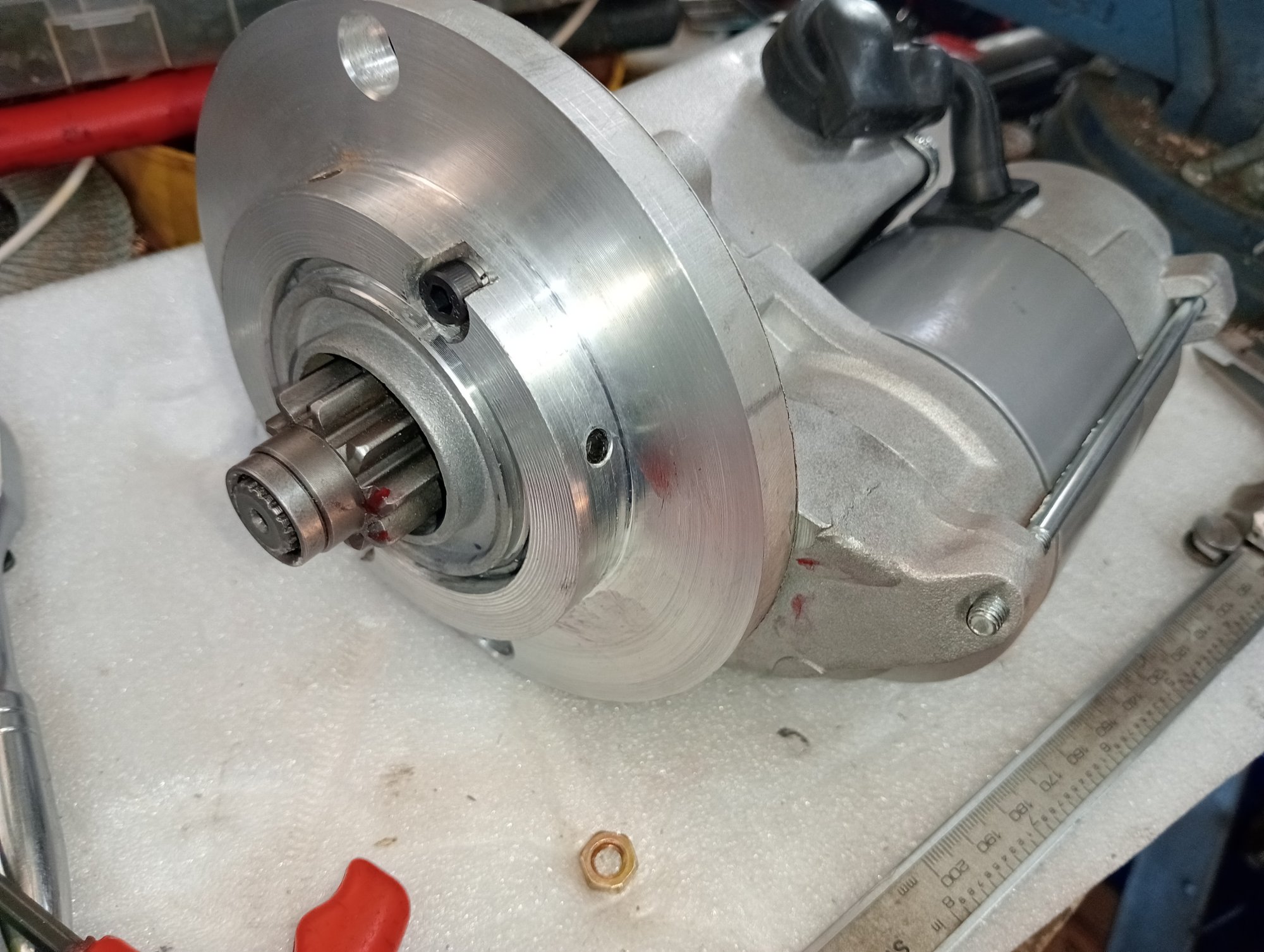
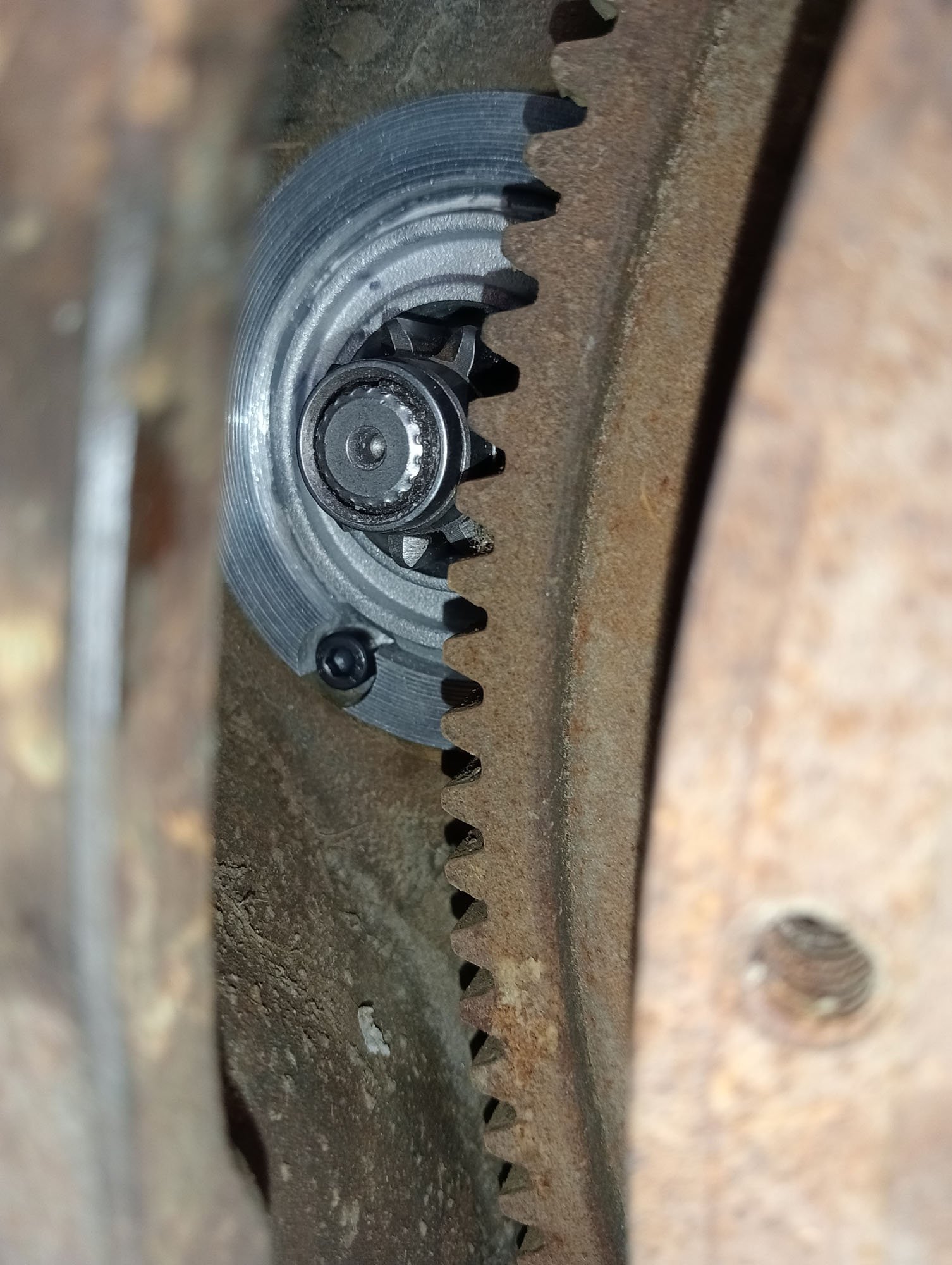
Packard Starter motor = unobtanium. These things ended production about 1953. If you were lucky enough to find one it would either cost a fortune or cost a fortune and need rebuilding. Any starter motor with the right pinion gear can be made to fit just about any engine, so looking up photos of Packard starter motors I see they have a 9 tooth pinion gear. A Hilux starter has a 9 tooth pinion so I dismantle the starter & check the pinion gear against the Packard flywheel & it fits perfectly. All I had to do was modify the gear housing of the starter so that the gear would mesh at the full tooth depth & make a new flange to fit the Packard bellhousing.
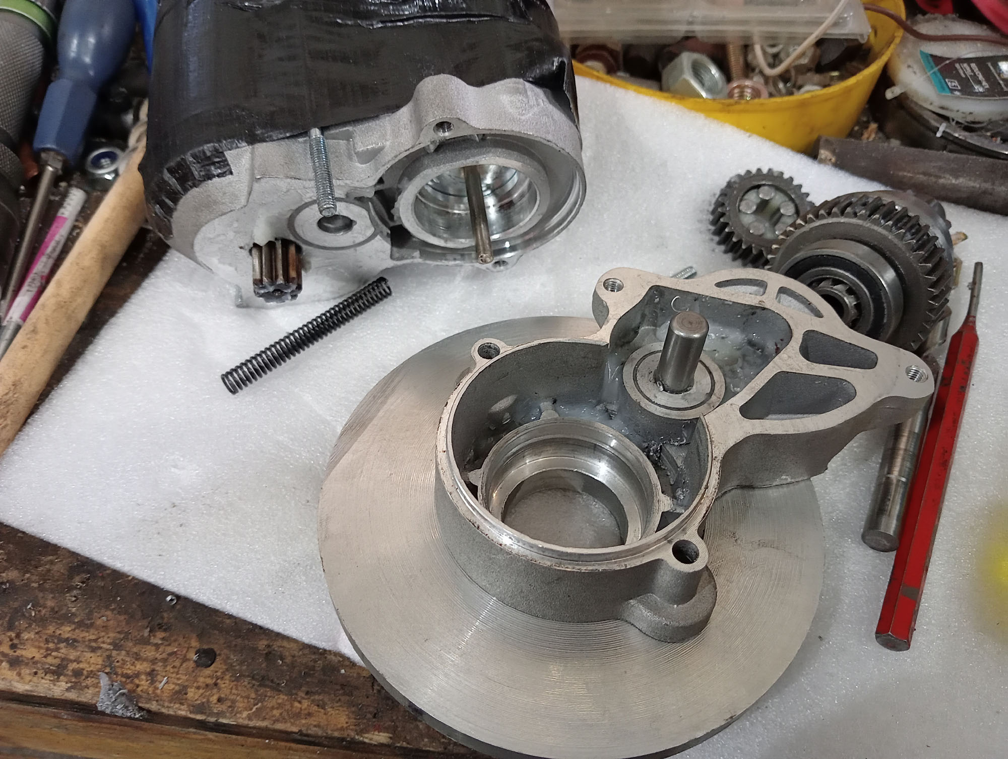
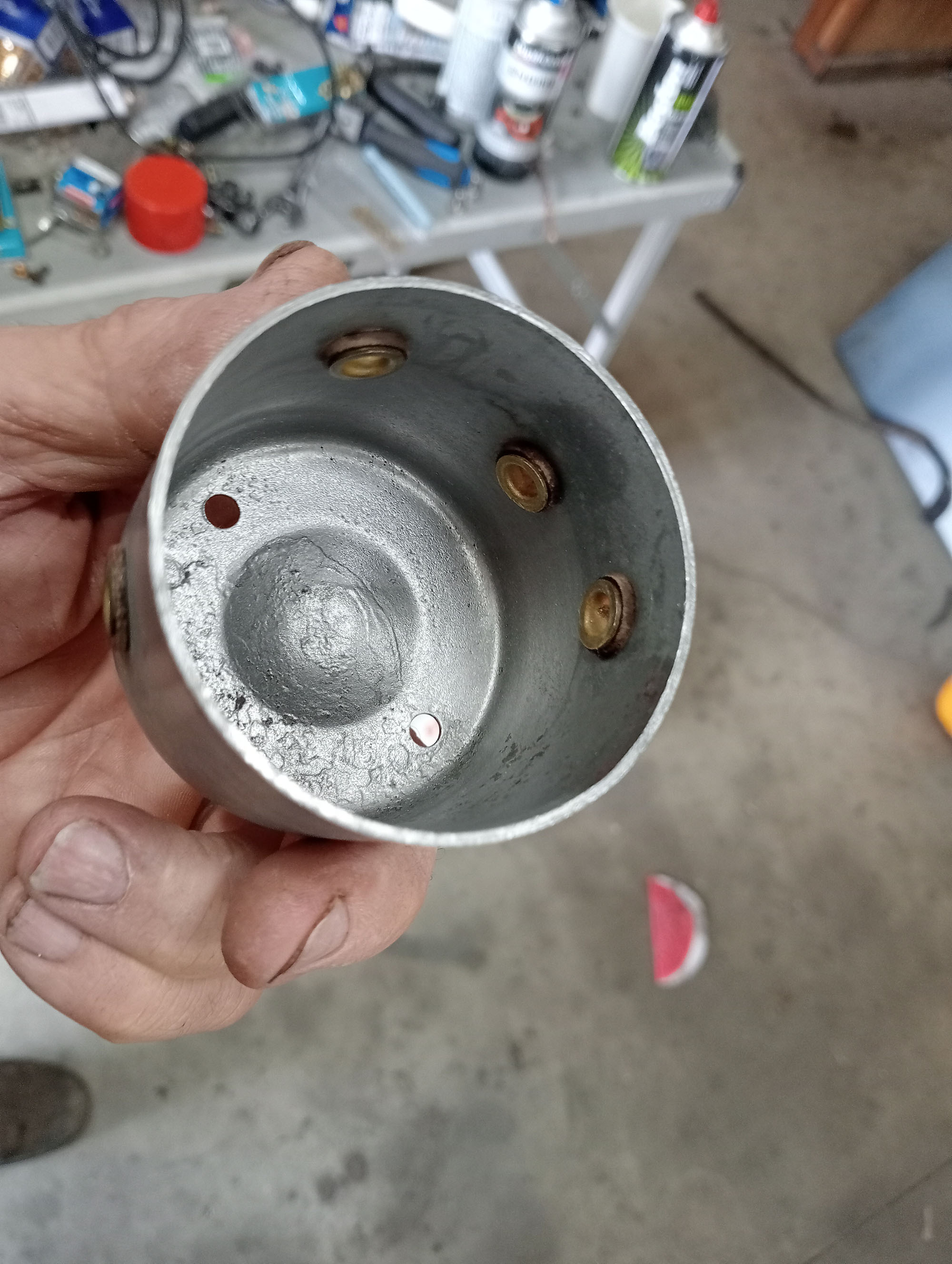
Machining off about 10mm from the gear housing to allow room to fit a new flange mount to suit the Packard bolt holes, A simple adapter plate would have moved the gear too far forward
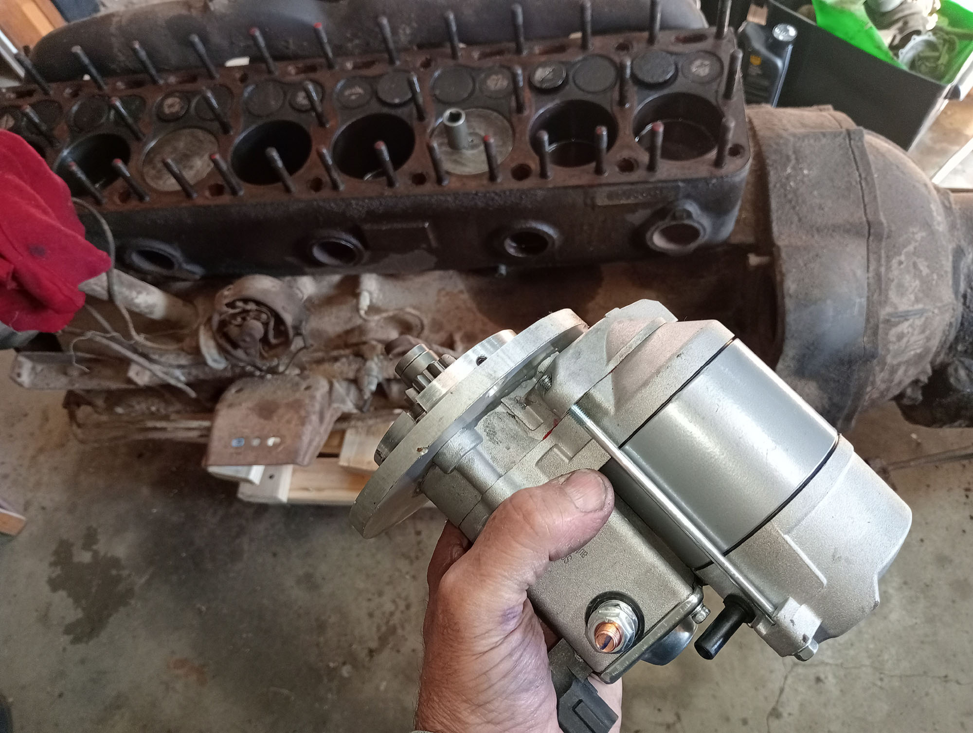
These are geared or Hi-Torq starters and are tiny in comparison to an original starter and much more powerful. The 4 cylinder starter has no problems cranking this monster straight Eight.
Wiring
For such a basic car with a bare minimum electrical system the wiring does look busy. The vintage Lucas ignition / light switch is from a Royal Enfield motorbike and isn't designed to carry the current loads of a car so I added a 100amp relay into the ignition circuit, 30amp relays for Low & High beam .
Wherever practical I've used old style lug connecters with rubber insulators and vintage cloth covered wire in my wiring loom ( thanks Graeme) and not wanting to hide it by wrapping in my favourite Tesa tape I used a waxed cord cable lacing method that I was taught in my first year Telecom apprenticeship , about (cough) 45 years ago. Pretty much just like trussing your sunday roast.
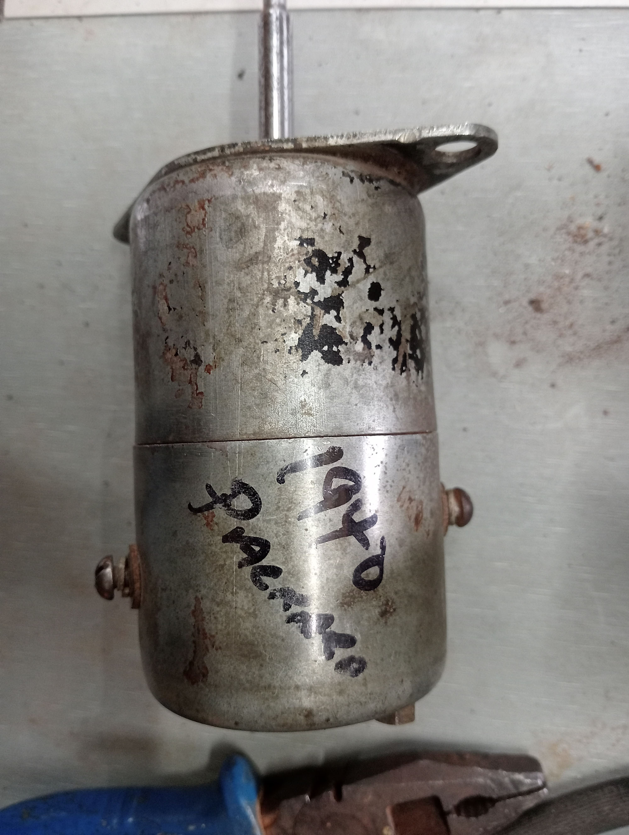
No production car I know of (apart from EV's) ever had a DC-DC converter but this car is a combination of American & English parts, as were the original Railton cars, Typically English cars were 12V from the beginning and American cars were 6V well into the 1950's. I could have gone either way but because I did not have a Starter motor or Generator to suit the Packard engine I used what was on hand, fitting a Toyota Hilux starter and Alternator dictated that this car will have a 12V electrical system, However the Packard - Borg Warner R9 Overdrive has a 6V solenoid so I wired in a 12v to 6v voltage converter to charge a small 6V SLA battery to keep the solenoid happy.
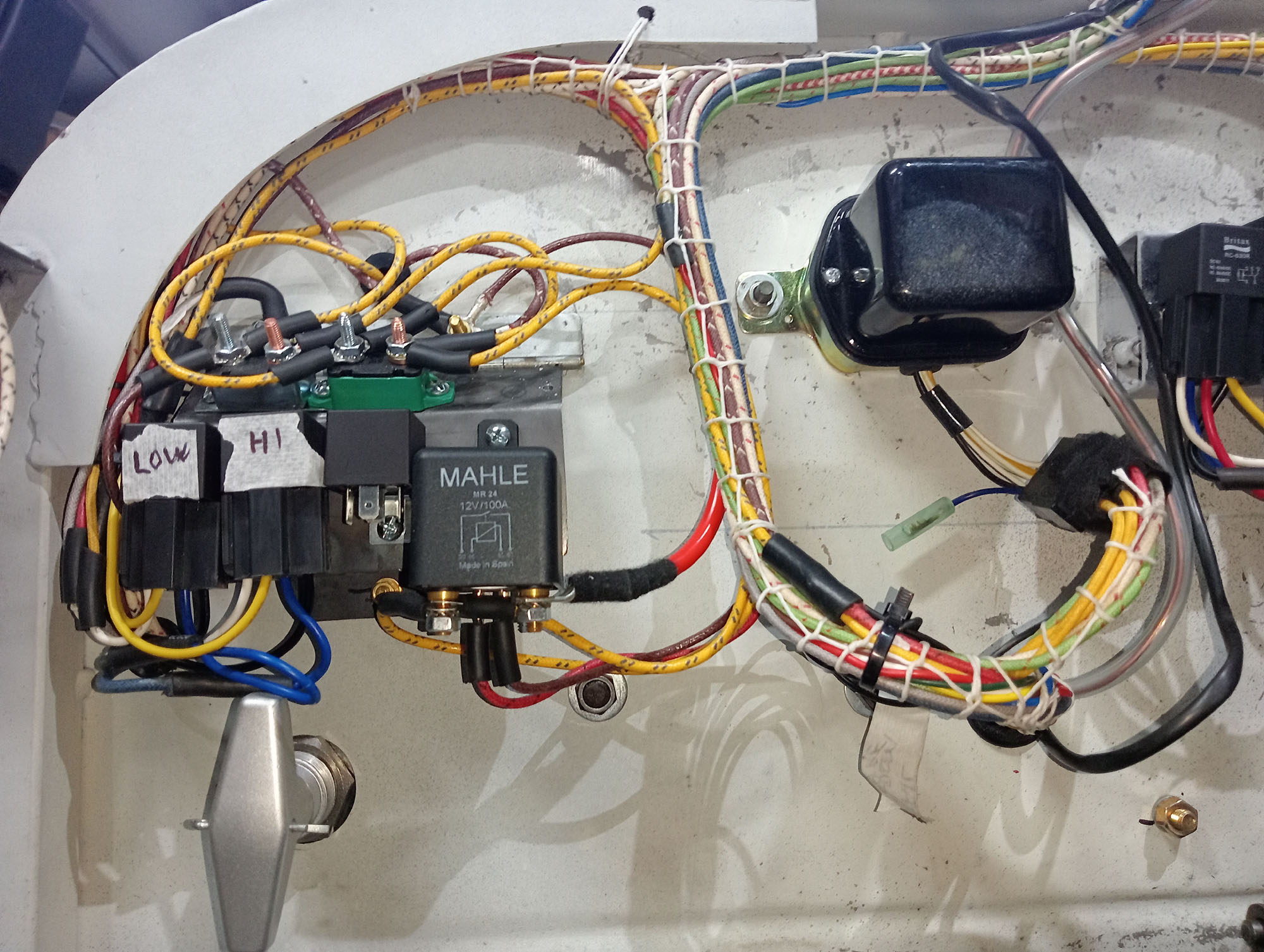
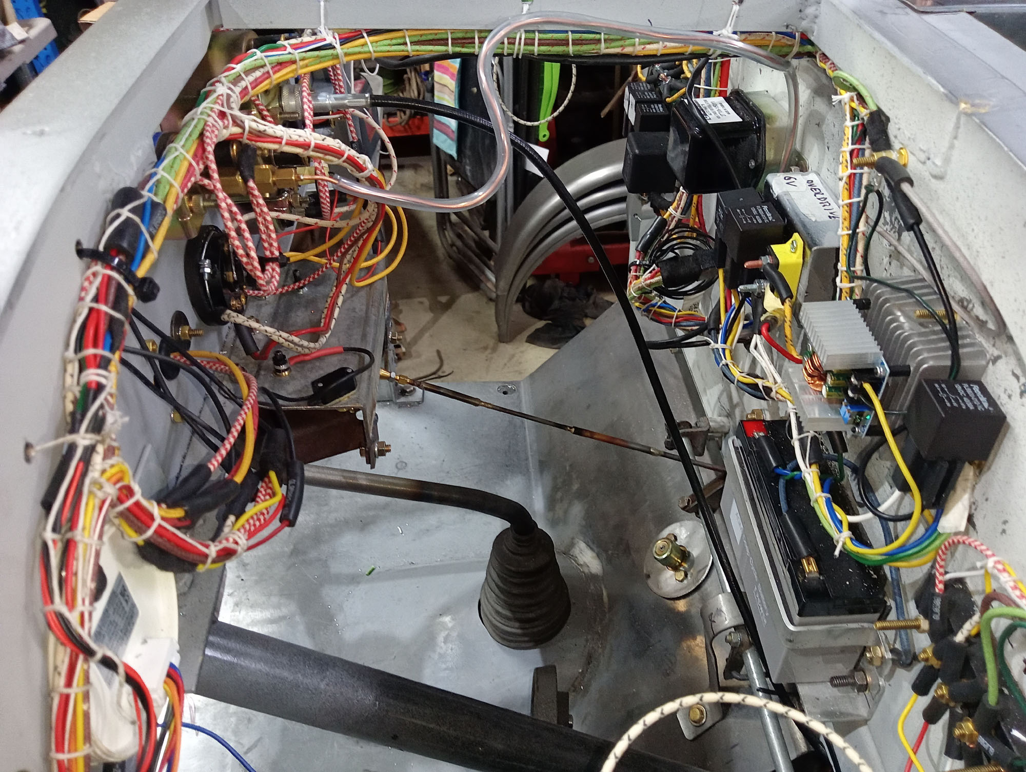
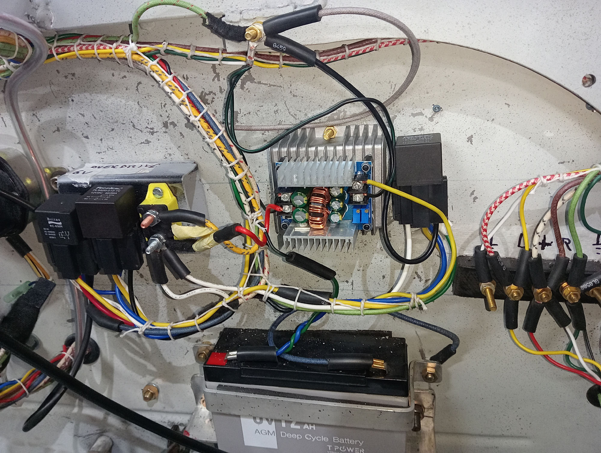
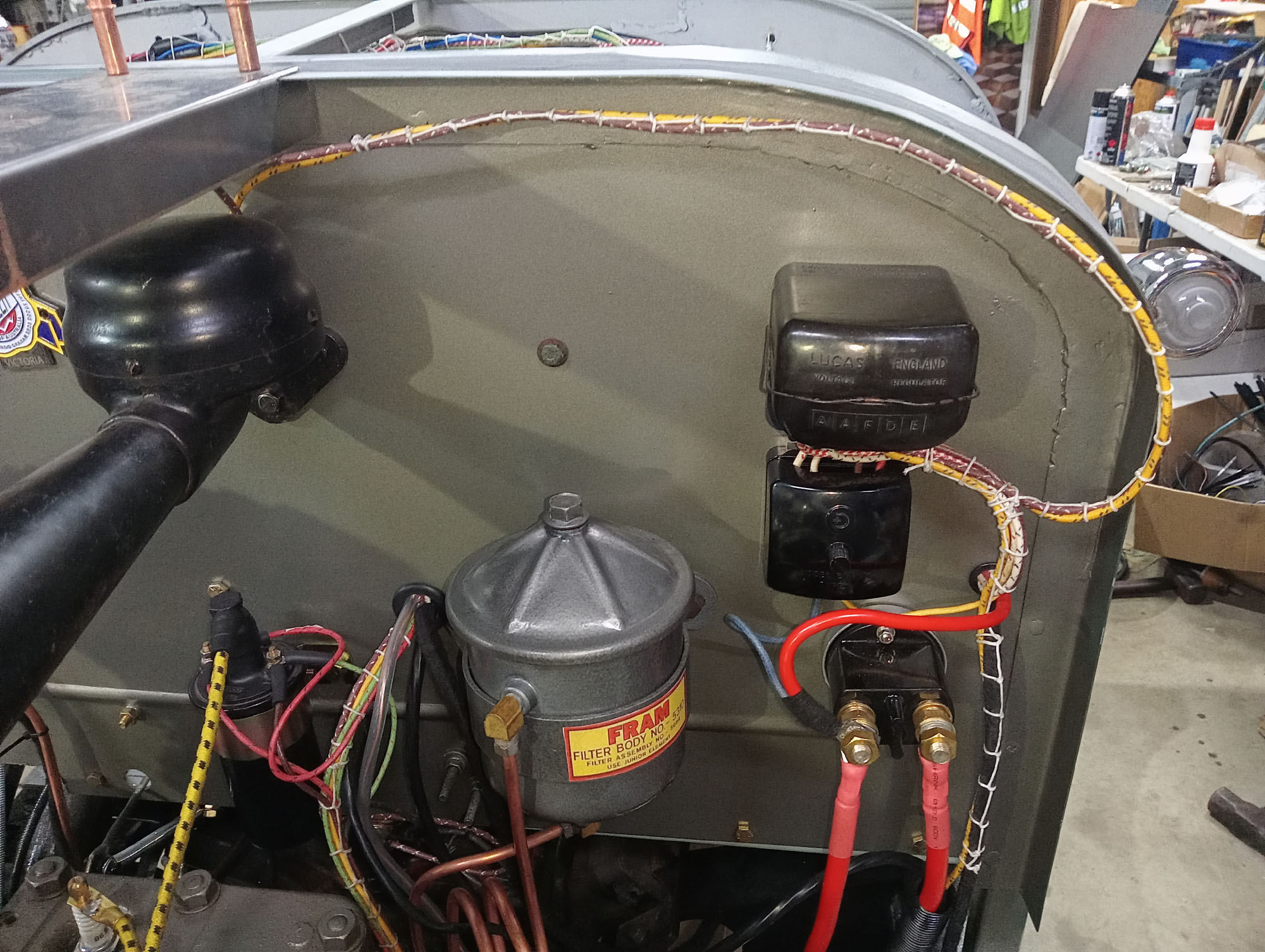
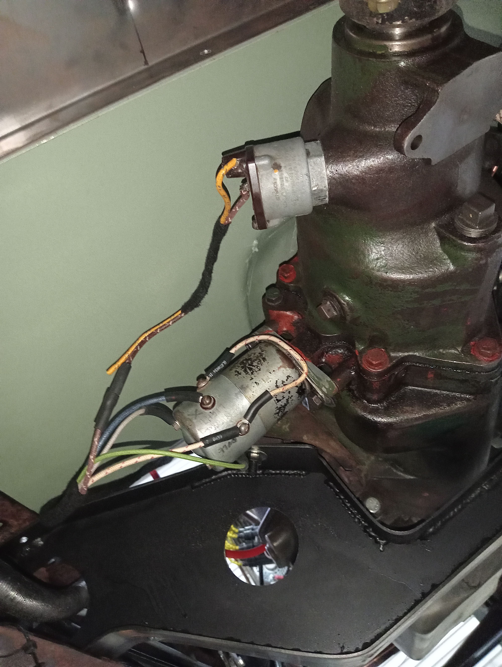
The horn is unique, never seen one before and google brings a blank, Its a heavy cast Lucas 12v unit, have no idea what its from but sounds like a mini fog horn. Relays for the Fuel pump & horn are inside the old Lucas Bakelite regulator box and a Bakelite Fuse box is below that. The electrical system is well protected with fuses & circuit breakers.
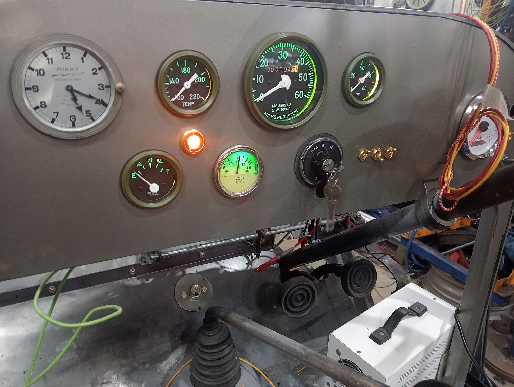
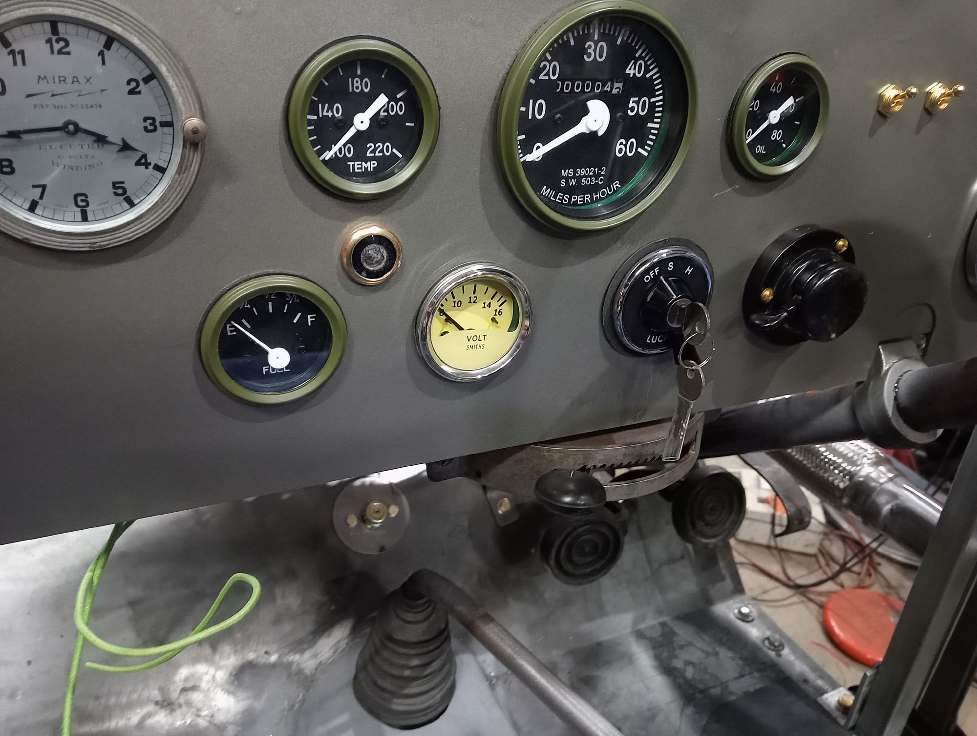
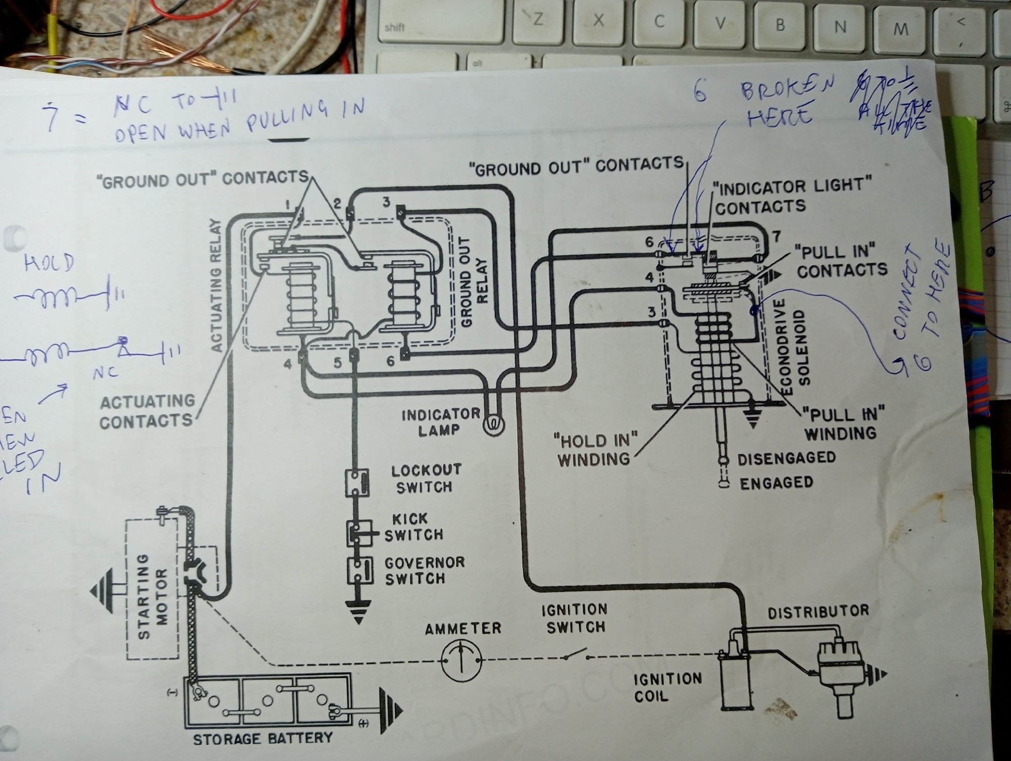
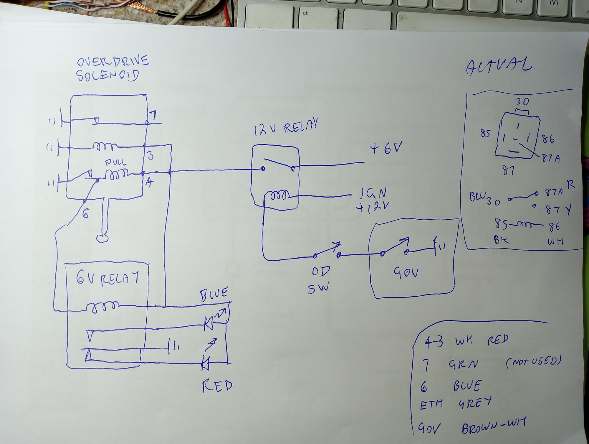
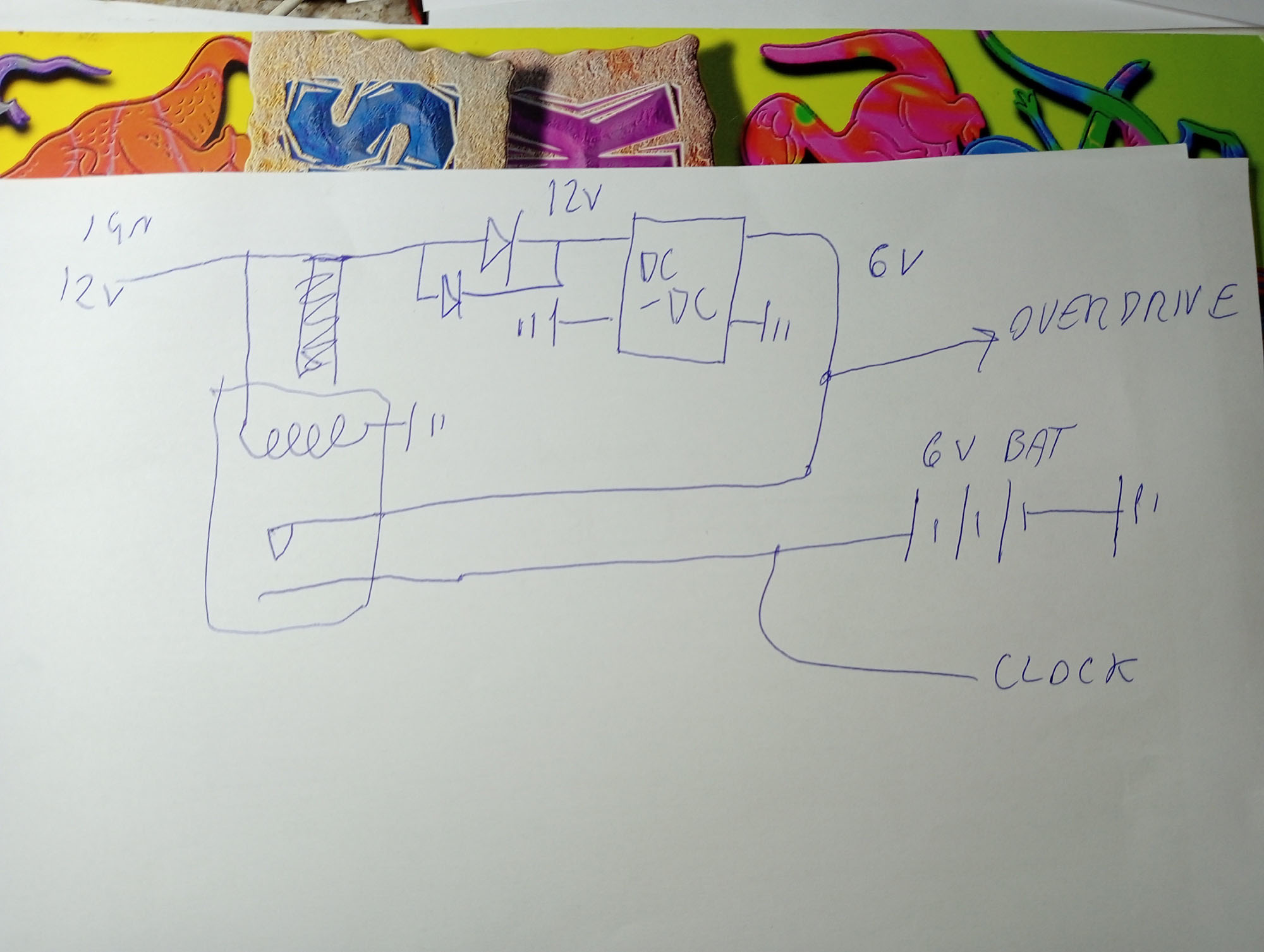
I usually wire up cars freehand without wiring diagrams which is great until a few years down the track I want to change or add something & have no bloody recollection of what I did so this time Ive drawn diagrams of the sections that are unique to this car. I had to deviate from the original Packard wiring as my OD Solenoid has a broken contact point & to allow for hybrid 6V-12V setup. Good thing too as a Packard Overdive relay is about $700 , I used two $10 relays.
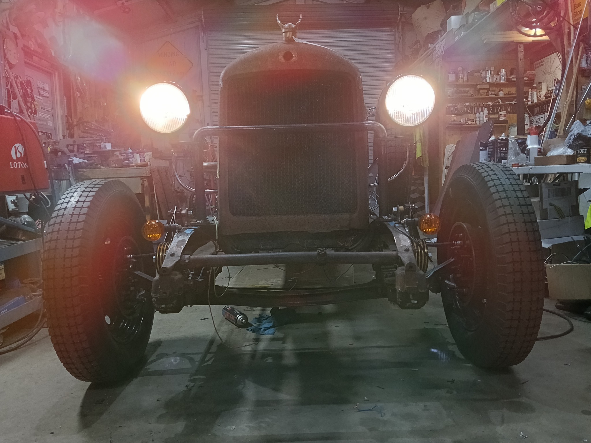
First time out of shed
Officially a car - First movement under its own power , out into the daylight. About 8 months into the project.
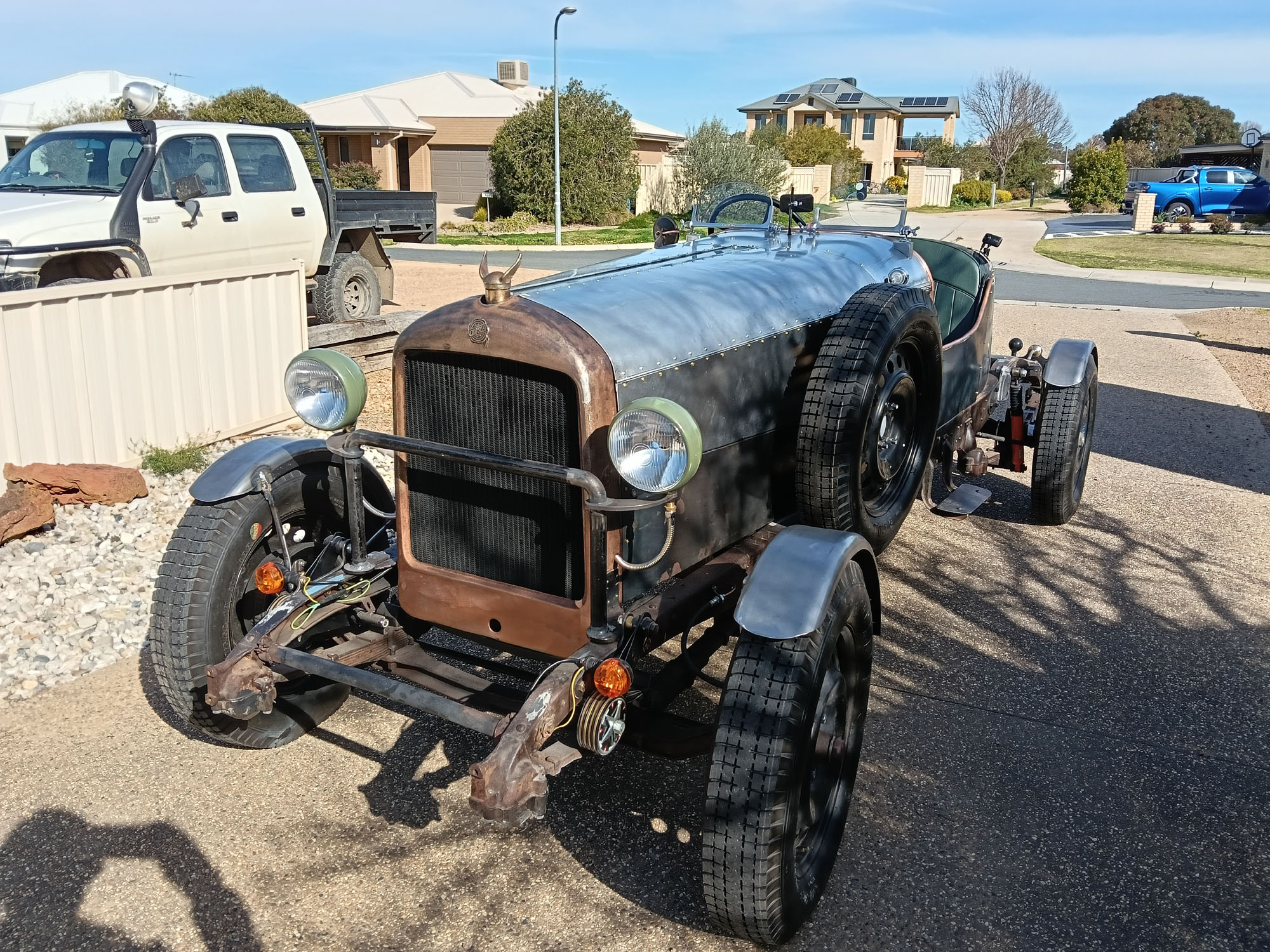
Lights
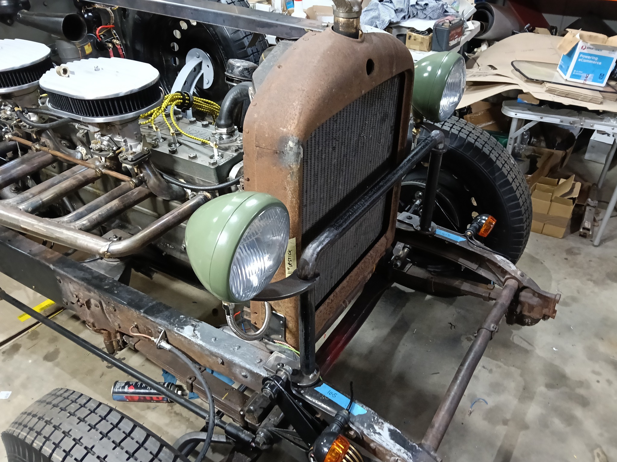
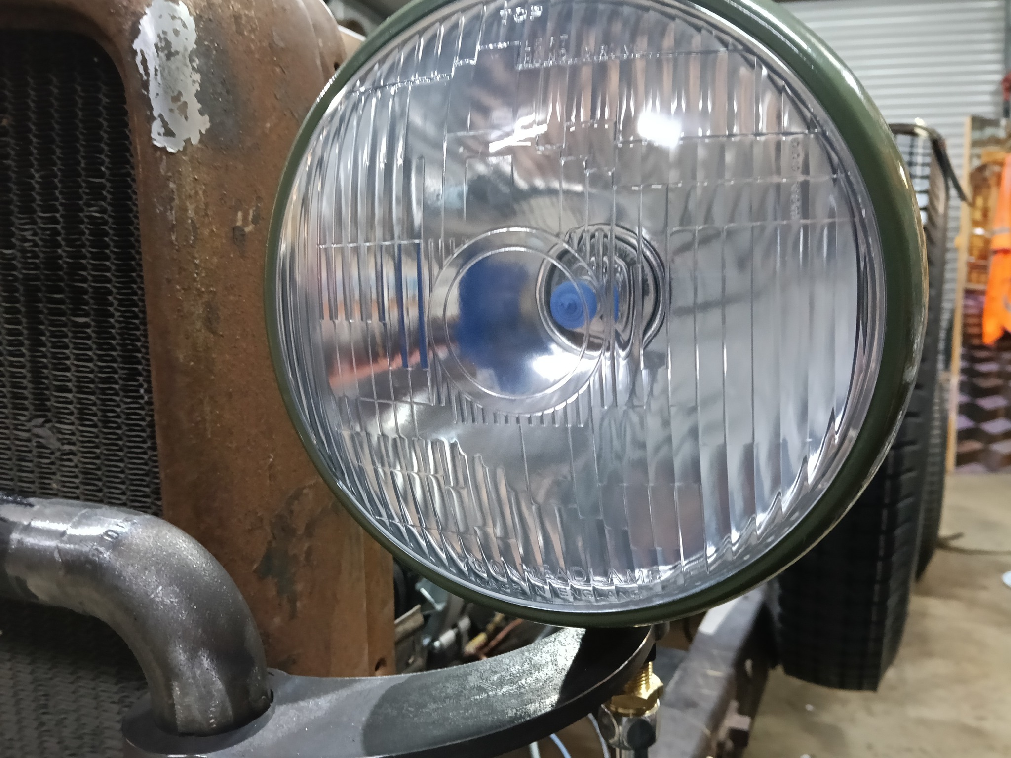
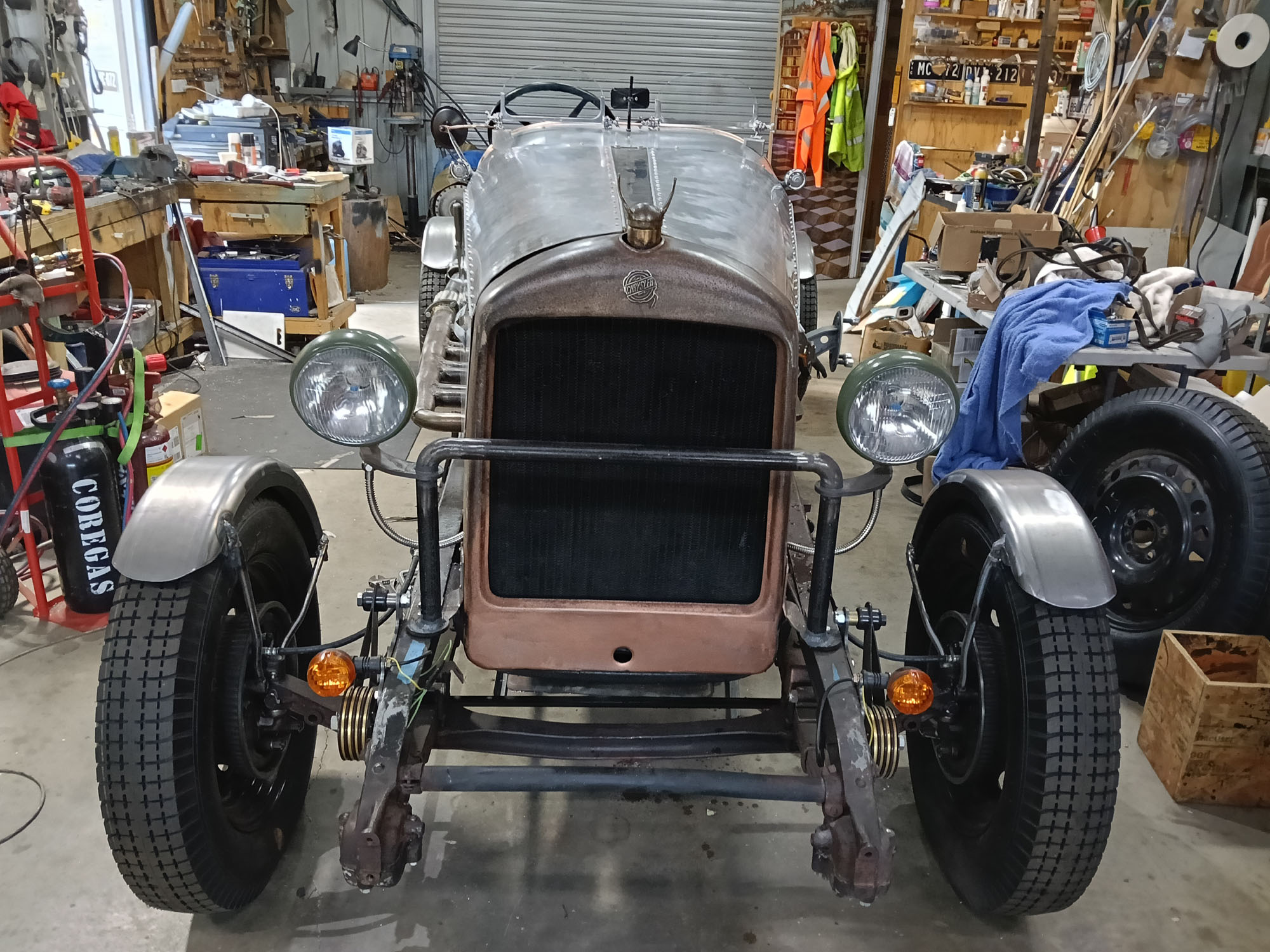
Headlights
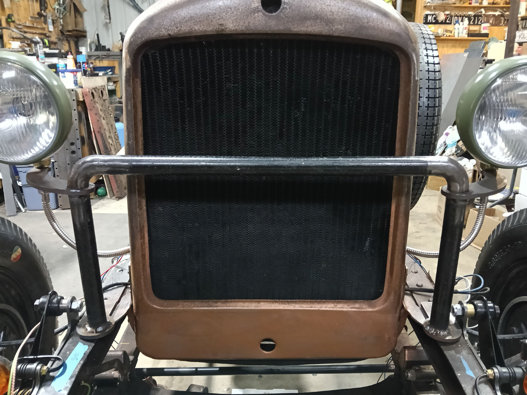
The Jewett radiator shell is not strong enough to mount lights on without causing stress and cracking, nor is there enough clearance to radiator for the bolts. Usually a light mounting bar would extend across the front of the radiator to help support the mudguards, but I'll be using cycle guards that turn with the wheels.
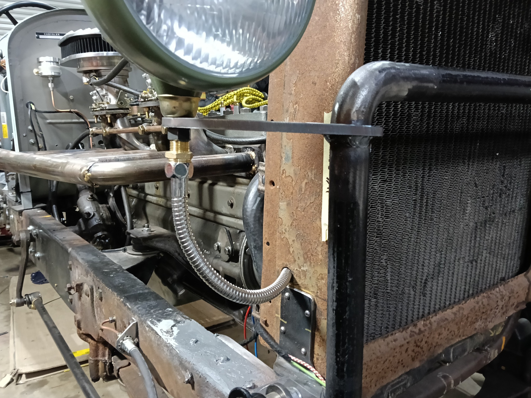
I made a light bar from 1" steam pipe with 8mm stanchions that curve around to mount the lights beside the radiator. That put the lights in about the right place to resemble a 29 Chrysler. - if you squint .
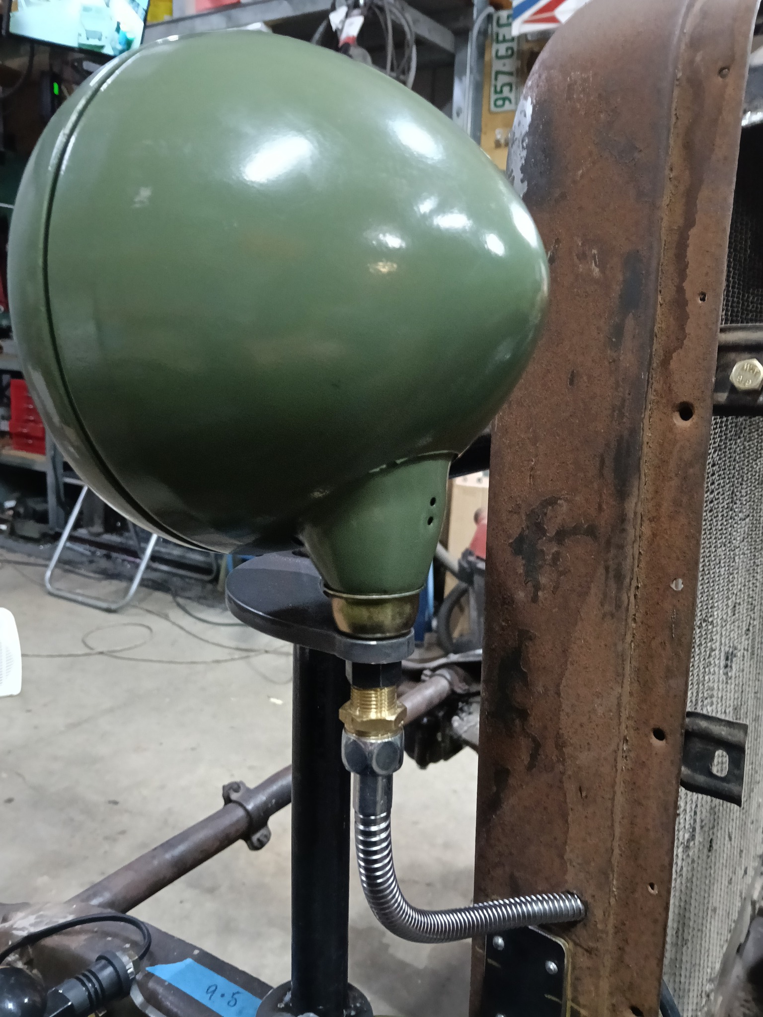
These are 7" Bullseye lookalike lights I had over from another project & mounted inside Indian housings. (Bullseye were a special Mopar 6 Volt light from the 1950's & can be found for about $1000 a pair )
I used water pipe fittings & bathroom shower hose for the flexi tube to pass wires through.
Some metalwork
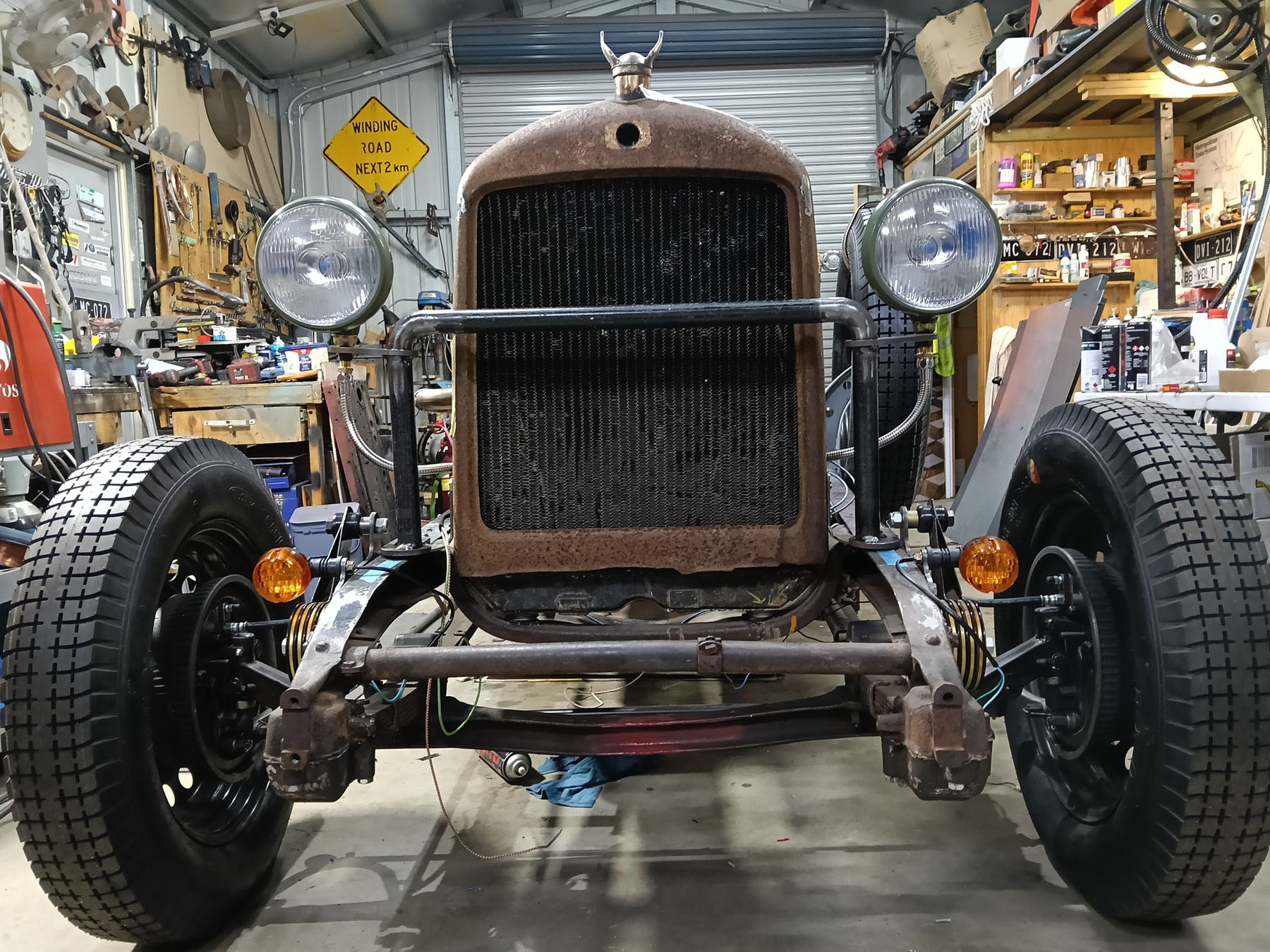
Whilst mounting the headlights I was reminded that the Radiator shell was missing the bottom part. I made a new piece from 1.6 sheet & welded in place. The welding looks ordinary as my visor was playing up - I was having trouble seeing where I was going .... but isn't that why the grinder was invented 😅
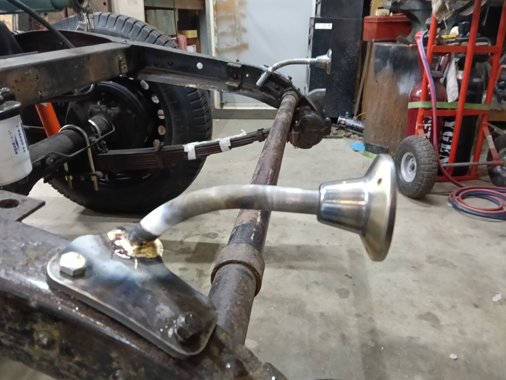
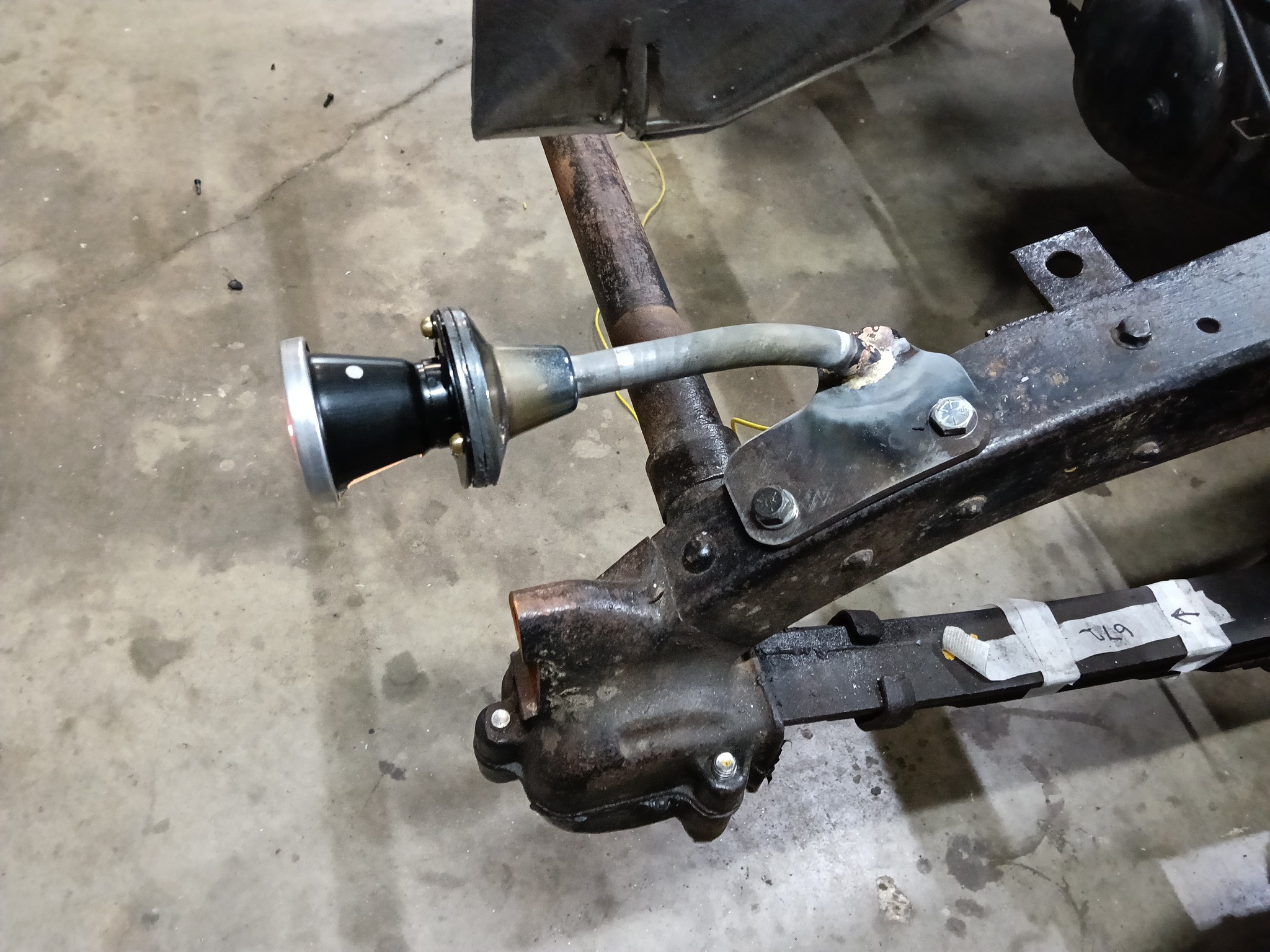
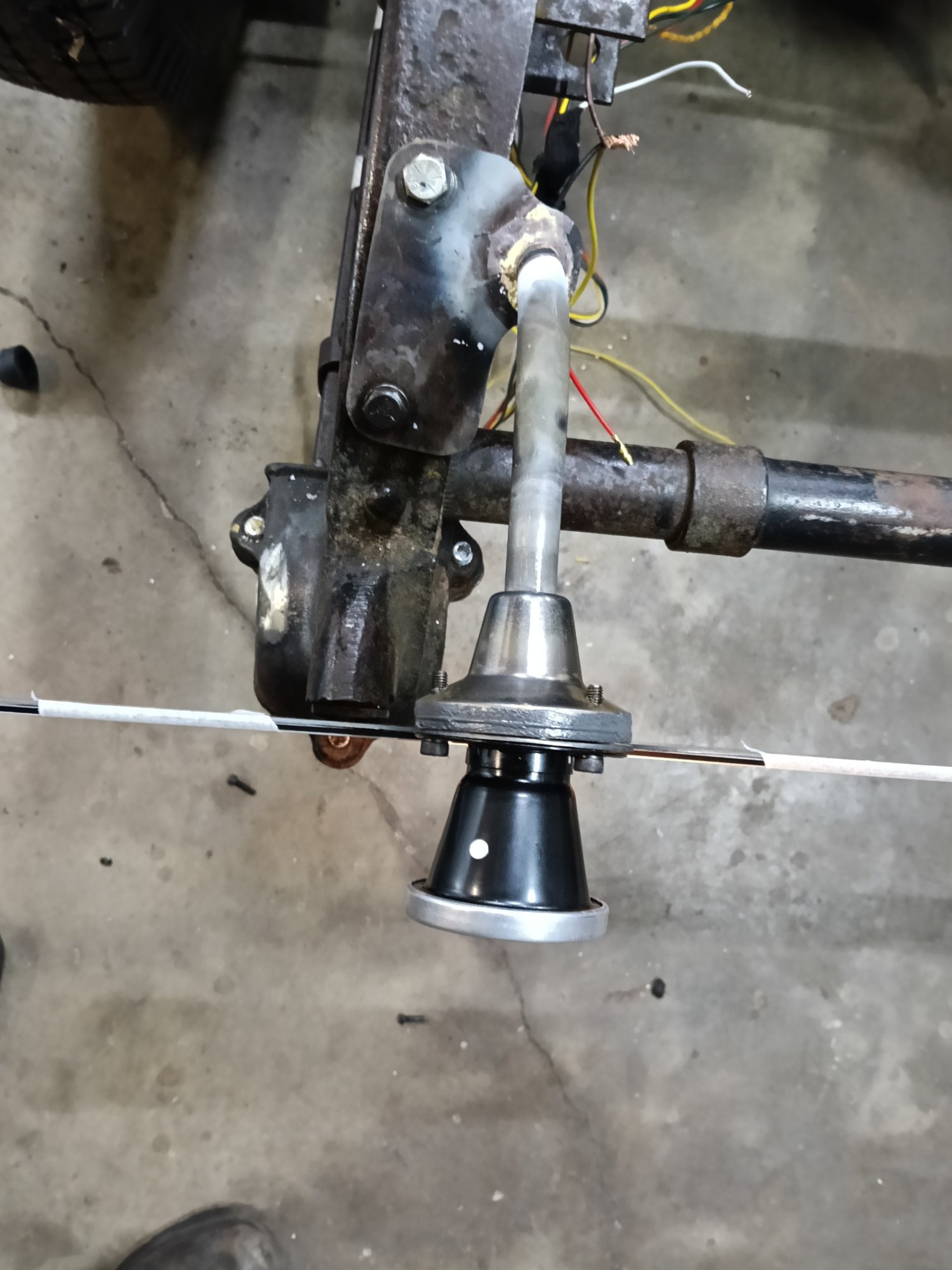
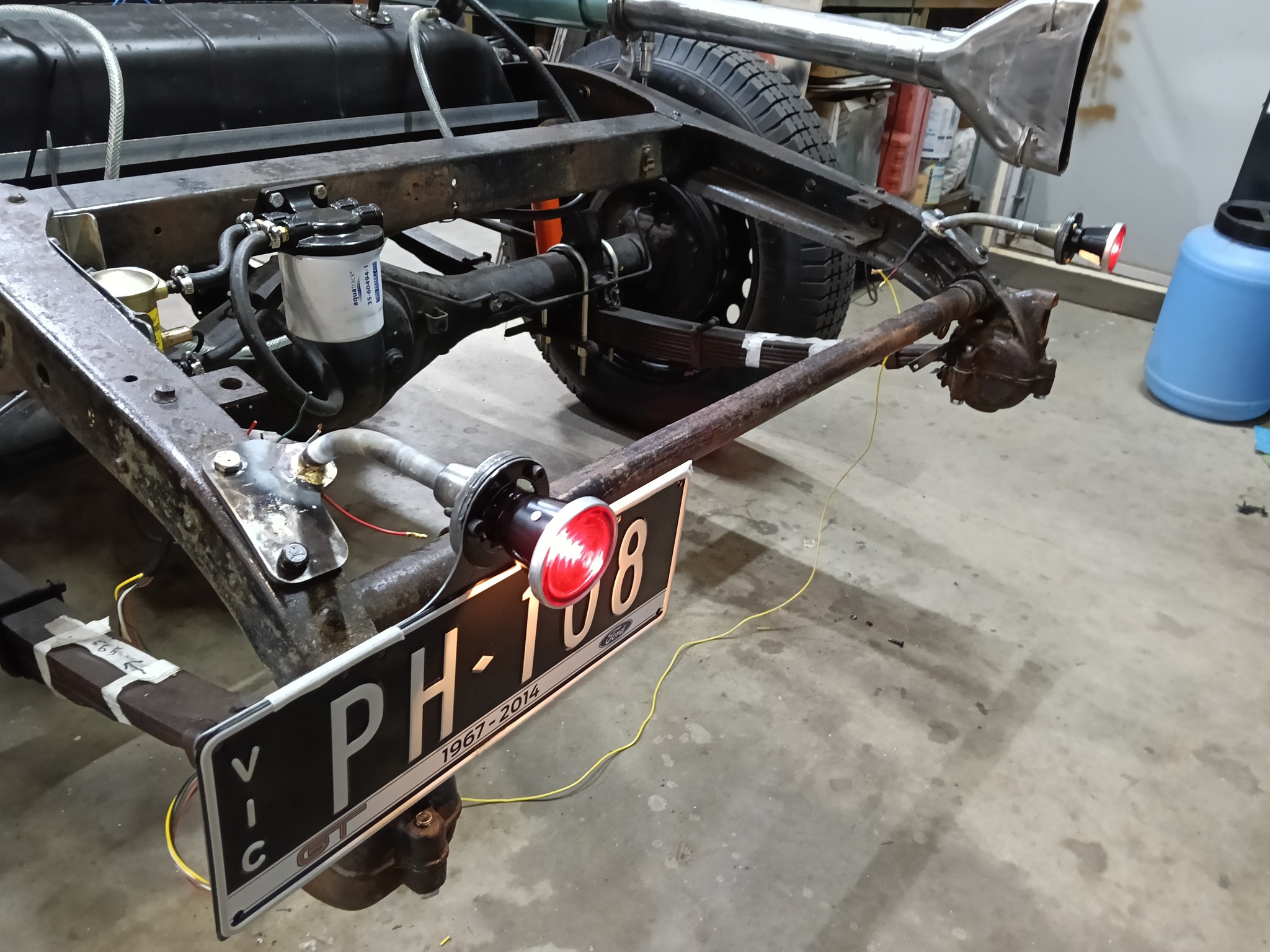
Tail Lights
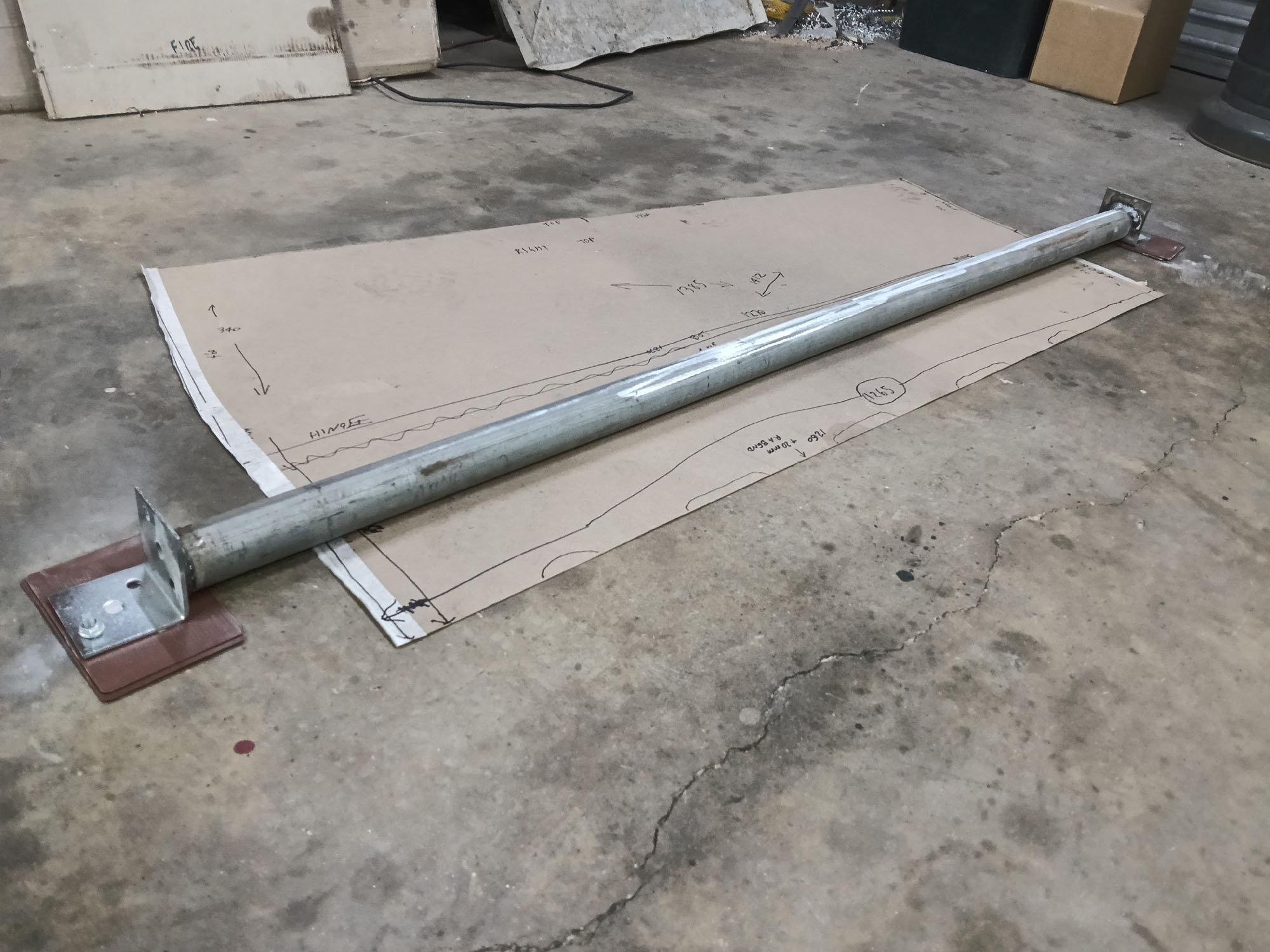
Raided the plumbing box again. Brass part to mount the tail lights seems correct for this car. Stalks are from gal steel pipe. I made some mount 8mm plates that bolt to existing holes in the chassis. Rock solid tail lamp stalks. The wires run inside the pipes. Reproduction Lucas 477 stop/tail lamps form an early British motorcycle suit the era. Number plate bracket in keeping with the style of car.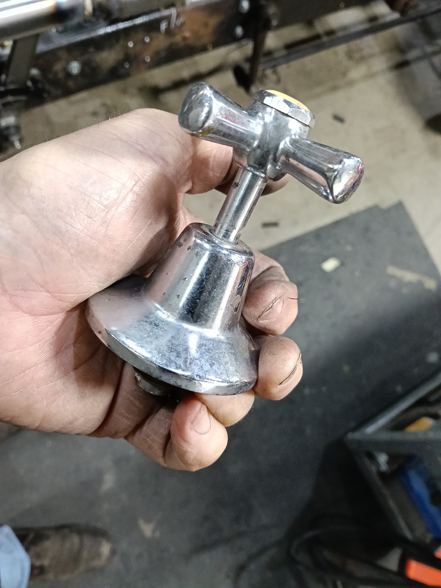
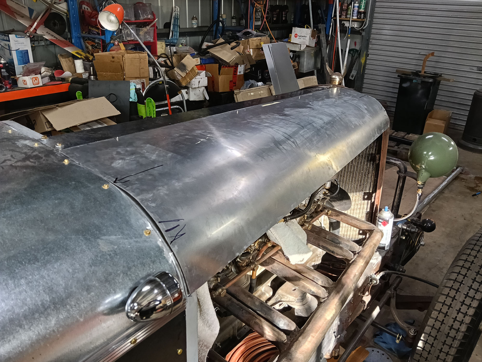
Body Building
I had planned on getting an Unreg Vehicle Permit to take the car for a spin to see if it had any mechanical problems but the weather was too cold & wet so started on the bodywork. Downside is it will be harder to fix problems once the body is in place, not a huge issue as it will need some dismantling for paint anyway.
I am not a skilled metalworker, from the outset one of the reasons the Railton Replica build appealed to me was its use of flat panels. The plan was to use flat panels & simple curves only, compound curves are out of the question ( I don't have room in the shed for an English wheel or other sheetmetal tools). I deviated early with a curved radiator shell so I used the same curve radius profile in the firewall / scuttle and 'door' openings
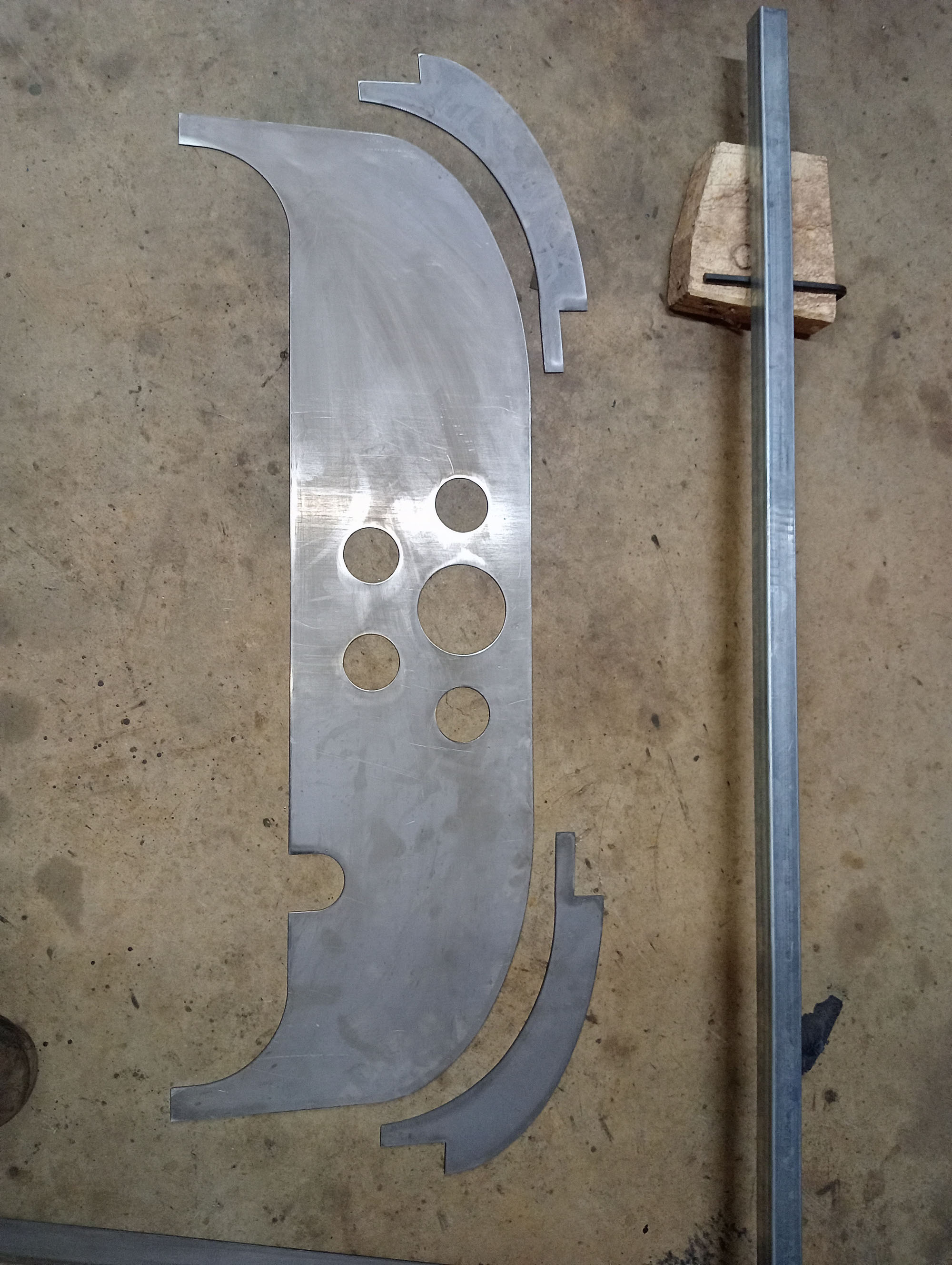
As with a lot of miscellaneous brackets and fittings on the car I drew all the body parts in CAD and plasma cut from 1.6mm steel sheet, except for the bonnet which is from 1.6mm 3003 Aluminium sheet and cowl top from 1.0mm gal sheet.


To replicate the looks & style of the Railton Replica, the rear of the car needs a boat tail, I had an envisioned a VW Beetle or Morris bonnet but when I picked up the Packard engines Frank pulled a Peugeot 203 bonnet from his stash and donated to the cause.


At this stage I moved the car out of the confined space of the shed to stand back and have a look at the body lines & see if its all in proportion,
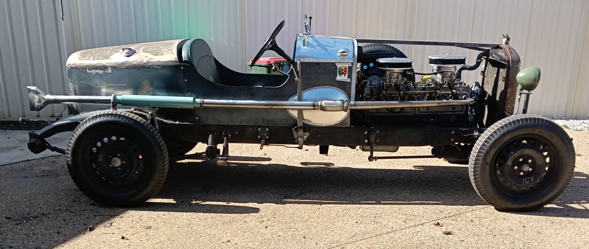
Next stage of the body I need to actually shape some sheet metal to make the bonnet, up till now I've just used flat sheets. I decided to make the bonnet from 1.6mm aluminium as I'm familiar with it after working on Land Rovers for 45 years. I don't have any metal rollers so welded some brackets on the end of a cyclone fence post so that it sat just 2mm above the floor.
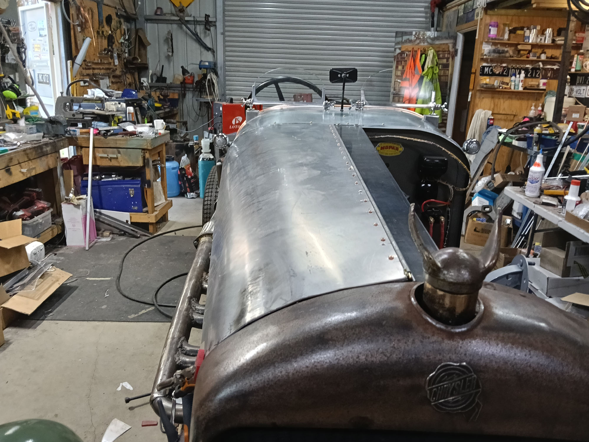
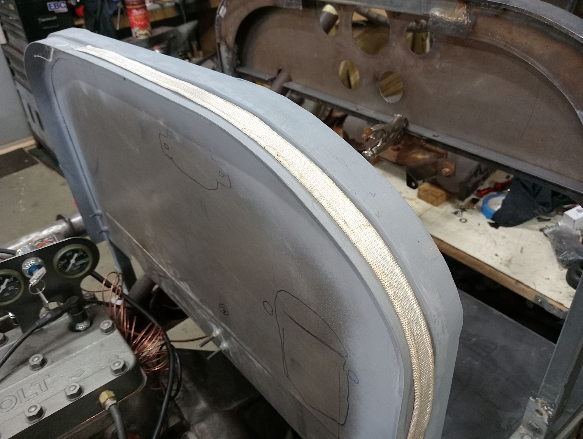
To finish off the body I need some trim or coaming around the open cockpit edges, I used 5/8" copper pipe which I first bent to shape then carefully cut a 1mm slot so that it could be fitted over the sharp edges of the cockpit. This not only makes it safer but considerably stiffens up the body sides.
100 years ago the copper edging would have been soldered to the sheetmetal but I opted to fill the pipe with Automotive Sikaflex and push it into place. The result is better than I had hoped. I did the coaming in 3 sections with joiner pieces so that the Cowl lid could be more easily removed if ever necessary..
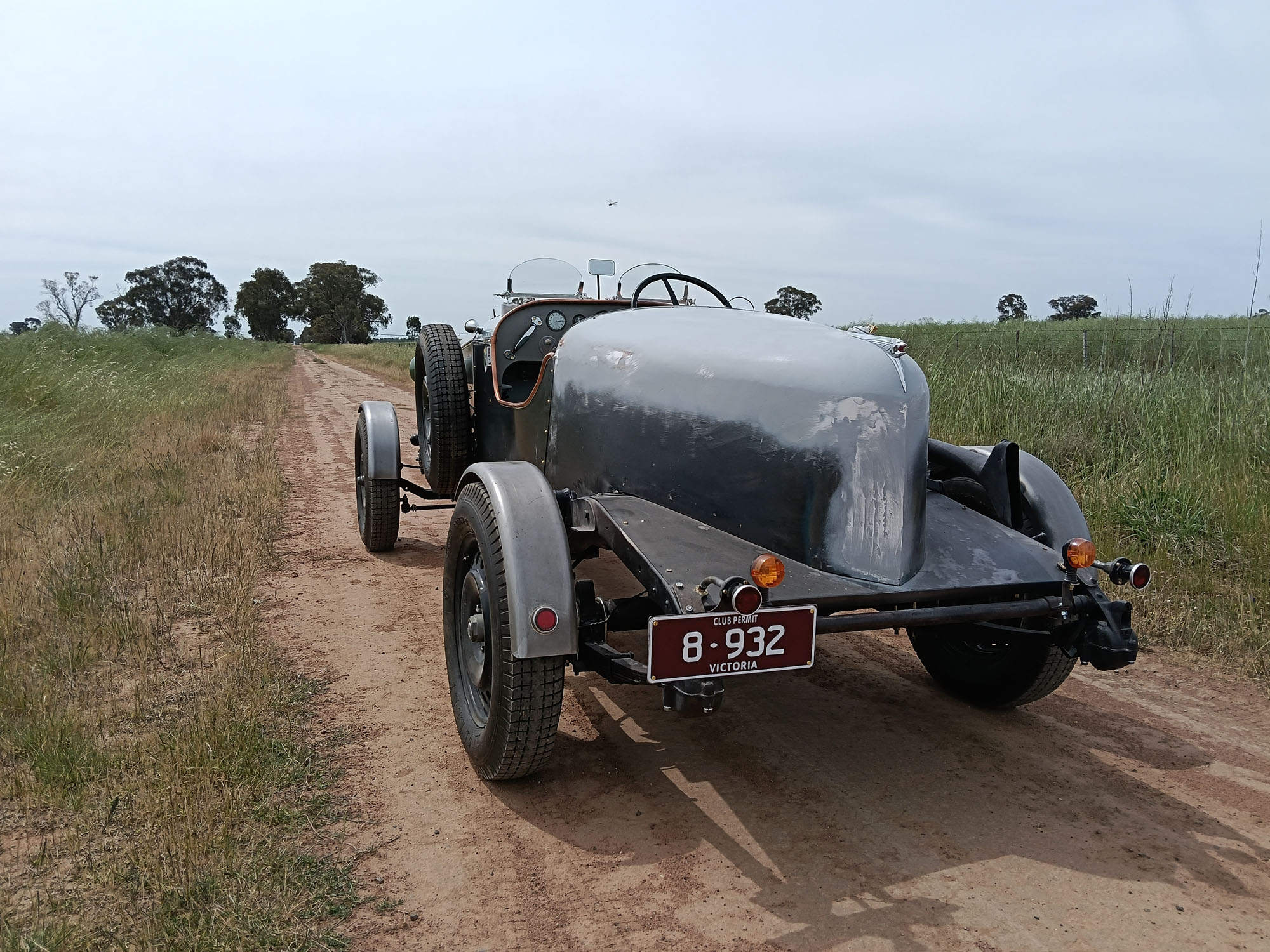
First Drive
September 6 2025. Less than a year from inspiration to road testing. Not a bad effort for a bloke in a shed on a first time Speedster build. I thought this project was going to take 10 years.
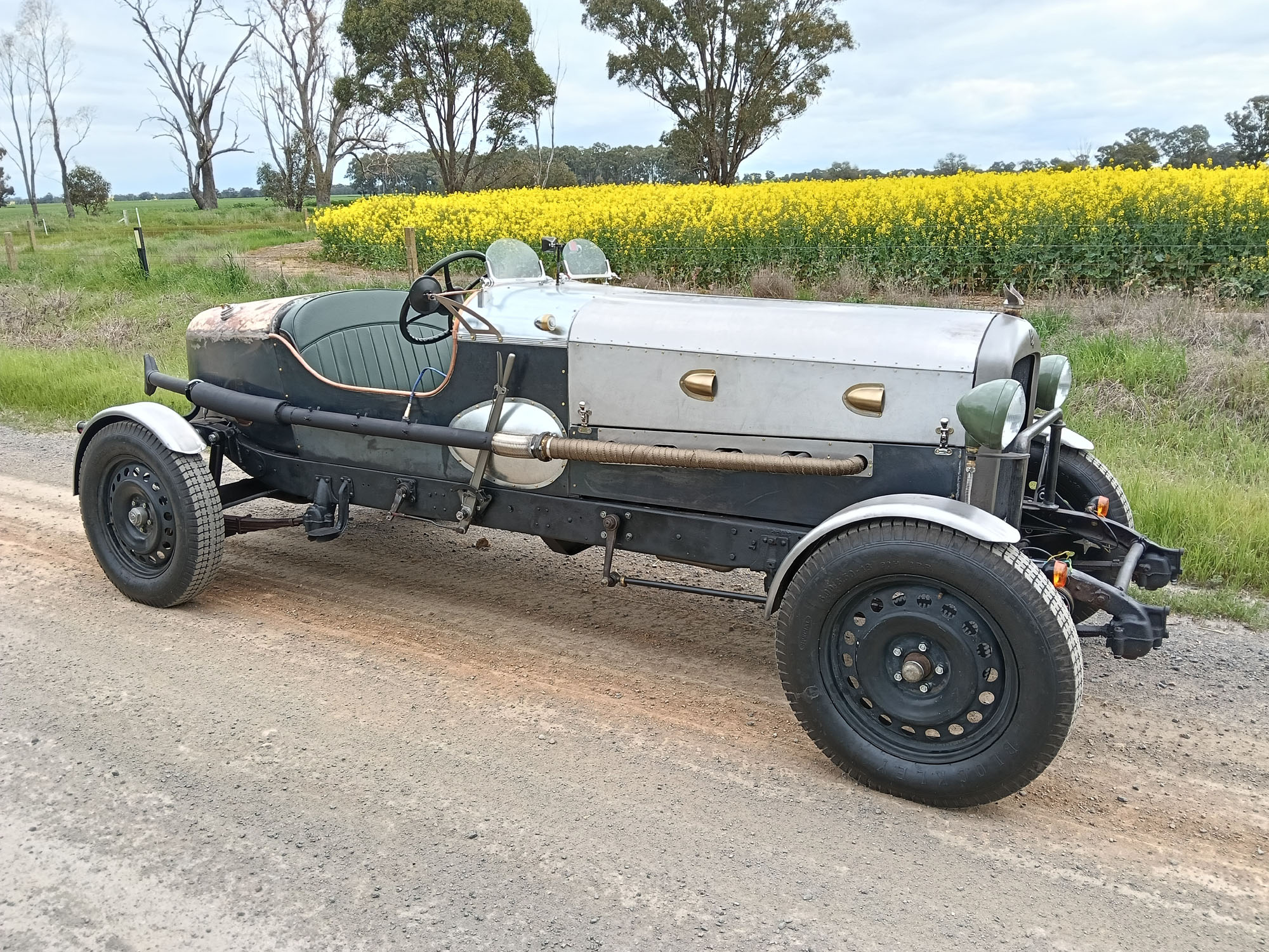
I had the ignition timing too retarded on the first drive around the block and the exhaust was way too noisy So I advanced the timing and made a new muffler that had more of a curve & fitted closer to the rear body. Second road test was a complete success & the car is everything I'd hoped for and so much more, so fun to drive. That Packard Straight Eight has such a fantastic note right though the rev range , It's so torquey pulls like a train from walking speed in top gear right through to max RPM. Book says 4000, 3500 is plenty for me.
Once road tested & tuned it was time for the Red Tape. I took the Car for a Road Worthy inspection & it passed first go & with the necessary club documents & proof of past rego in hand VicRoads was painless & presented me with the Number Plate.
A couple of videos
A couple of drive by clips.
360 camera on the car
last updated Dec 30 2025
Hand coded on Linux using Bluefish open source editor
